Stability-enhanced traction and yaw control using electronically controlled limited-slip differential

a technology of limited-slip differential and stability enhancement, which is applied in the direction of non-deflectable wheel steering, gas pressure propulsion mounting, registering/indicating working of vehicles, etc., can solve the problems of reducing the stability of the vehicle. , to achieve the effect of improving stability and enhancing vehicle lateral dynamics

Active Publication Date: 2010-09-21
EATON INTELLIGENT POWER LTD
View PDF80 Cites 21 Cited by
  • Summary
  • Abstract
  • Description
  • Claims
  • Application Information

AI Technical Summary

Benefits of technology

[0008]An embodiment of the present invention includes an active stability control method using ELSDs to enhance the vehicle lateral dynamics while preserving longitudinal motion. Another embodiment of the present invention includes a control system that provides stability enhancement of the traction control. The stability-enhanced traction control was evaluated under the condition of straight-line full-throttle launching on a split-μ ice / asphalt surface. The experimental data shows a significant stability improvement in the traction control operating mode.

Problems solved by technology

Typical traction control systems based on brake intervention have the disadvantage of dissipating an amount of energy roughly equal to that spent in biasing the high-friction wheel.
For example, when a vehicle attempts to accelerate or climb on a split-friction (split-μ), low-high friction surface, it often loses its energy to the braking system by dissipating the same amount of energy it biases to the high-friction wheel.
Hence, the braking torque limits the driving torque on the high-friction wheel and is often insufficient to move the vehicle, such as in an uphill-driving situation.
Fully locked differentials achieve the best possible longitudinal traction but, on slippery or split-μ surfaces, the lateral dynamics of the vehicle may be degraded and deviate from the driver's intended direction.
However, brake-based systems suffer from the limitation that the speed performance of vehicle is deteriorated and conflicts with the driver's actions.

Method used


Image

  • Stability-enhanced traction and yaw control using electronically controlled limited-slip differential
  • Stability-enhanced traction and yaw control using electronically controlled limited-slip differential
  • Stability-enhanced traction and yaw control using electronically controlled limited-slip differential

Examples


Embodiment Construction

[0022]The present invention will be described as follows. First, an exemplary vehicle driveline configuration using an electronically controlled limited-slip differential will be introduced. Second, modeling of a limited-slip differential is analyzed. Third, a stability control system is described for both traction control and yaw control. Finally, simulation and experimental results will illustrate the effectiveness of the control system to control vehicle stability during launch and relatively high-speed operation.

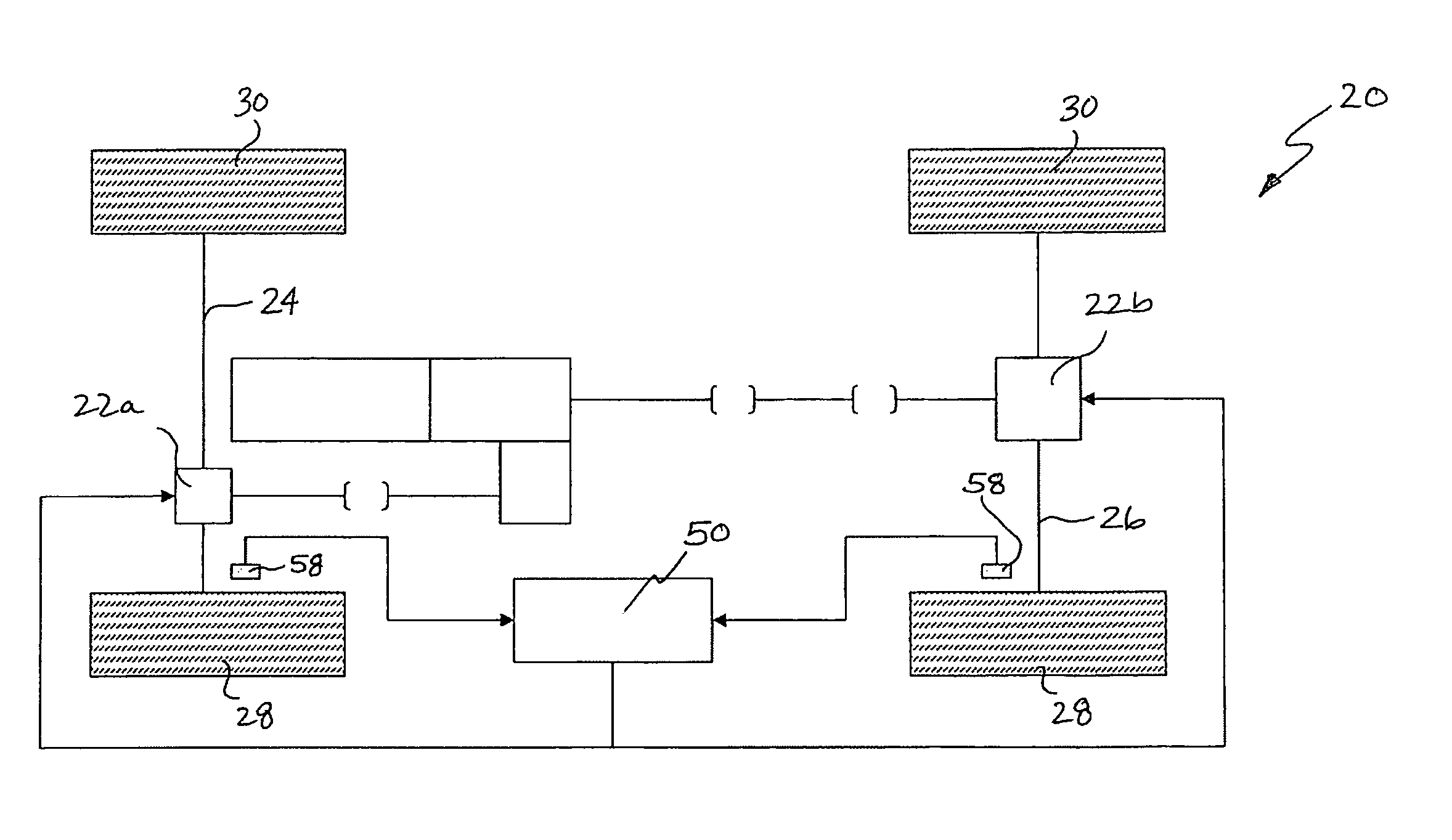
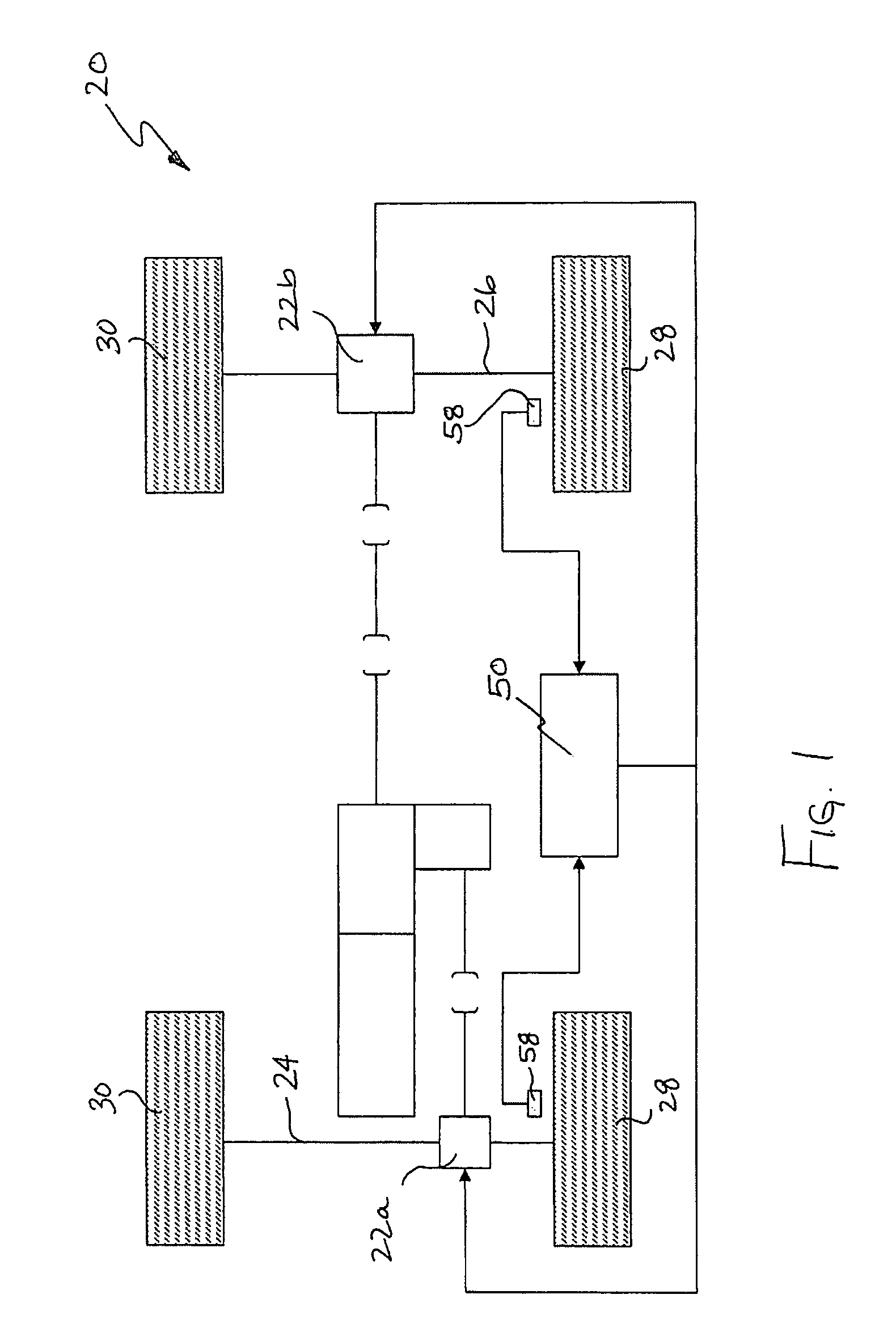
[0023]Referring to FIG. 1, a proposed driveline configuration 20 is shown, which is not intended to be limiting. Driveline 20 includes an electronically controlled limited-slip differential (ELSD) 22a, 22b installed in at least one of a front axle 24 and a rear axle 26. The ELSD 22 may be used to bias torque between left and right wheels 28, 30. In an embodiment, the amount of torque distributed between the left and right wheels 28, 30 by the ELSD 22 is determined by eng...


PUM


Abstract

A control system for a vehicle having first and second wheels is provided that includes a differential apparatus adapted to distribute torque between the first and second wheels and a traction controller for controlling operation of the differential apparatus from vehicle launch up to a predetermined vehicle speed. The traction controller is configured to engage the differential apparatus in a first operating state according to at least one vehicle operating parameter indicative of a low traction operating condition and to further control engagement of the differential apparatus in a second vehicle operating state during the low traction operating condition according to a difference between an actual vehicle yaw rate and a predetermined target vehicle yaw rate. The control system also includes a stability controller for controlling engagement of the differential apparatus at or above the predetermined vehicle speed.

Description

CROSS-REFERENCE TO RELATED APPLICATIONS[0001]This application claims the benefit of Provisional Patent Application U.S. Ser. No. 60 / 765,046, filed Feb. 3, 2006, in the name of Damrongrit Piyabongkarn, Jae Young Lew, John Allen Grogg and Robert Joseph Kyle for a “STABILITY-ENHANCED TRACTION AND YAW CONTROL USING ELECTRONIC LIMITED SLIP DIFFERENTIAL”.BACKGROUND OF THE DISCLOSURE[0002]The present invention relates to an active vehicle stability control system and method using electronically controlled limited-slip differentials to enhance vehicle lateral dynamics while preserving longitudinal motion.[0003]Anti-lock braking systems (ABS) have become an integral part of modern passenger vehicles and may be used to improve vehicle traction and stability. Typical traction control systems based on brake intervention have the disadvantage of dissipating an amount of energy roughly equal to that spent in biasing the high-friction wheel. For example, when a vehicle attempts to accelerate or cl...

Claims


Application Information

Patent Timeline
Patent Type & Authority Patents(United States)
IPC IPC(8): G05D1/00B60T7/12F16H48/08F16H48/20F16H48/22F16H48/30F16H48/32F16H48/34
CPCB60K17/16B60K23/04F16H48/08F16H48/22F16H48/30F16H48/34B60K17/34Y10T74/1435B60T2201/14B60W2520/10B60W2520/14B60W2520/26B60W2720/14F16H48/32F16H2048/204F16H2200/2071Y10T74/19274Y10T74/2188Y10T74/1254B60W10/12B60W30/02
Inventor PIYABONGKARN, DAMRONGRITLEW, JAE Y.GROGG, JOHN A.KYLE, ROBERT J.
Owner EATON INTELLIGENT POWER LTD
Why Eureka
Try Eureka