
Adaptive inertial particle separators and methods of use

a technology of inertial particle separator and inertial particle separator, which is applied in the direction of machines/engines, combustion-air/fuel-air treatment, mechanical equipment, etc., can solve the problems of increasing the frequency of engine repair and maintenance, affecting engine performance and reliability, and not providing adequate separation efficiency, so as to facilitate the entry of particles, and facilitate the passage of clean air

Active Publication Date: 2010-09-28
GENERAL ELECTRIC CO
View PDF19 Cites 28 Cited by
  • Summary
  • Abstract
  • Description
  • Claims
  • Application Information

AI Technical Summary

Benefits of technology

"The patent describes a system for removing sand and dust from the inlet of a gas turbine engine. The system includes a sensor to detect the concentration of sand and dust, and a deployable inflatable boot with fluid exit slots to prevent particles from entering the compressor. The system can operate in two modes: a first mode to remove sand particles and debris from the fluid, and a second mode to increase the removal efficiency of sand particles and debris from the fluid. The technical effects of the patent include improved engine performance, reduced maintenance costs, and reduced wear and tear on engine components."

Problems solved by technology

Sand and dust ingestion in gas turbine engines may adversely affect engine performance and reliability, and may also increase the frequency of repair and maintenance required for the engines.
For example, known inertial particle separator (IPS) systems perform well in any weather conditions, are highly reliable, are integrated into the engine, but may not provide adequate separation efficiency during severe sand and dust conditions.
However, the same features that facilitate the separation of sand and dust particles from the inlet air, also cause inlet pressure losses that may detrimentally effect gas turbine engine performance.
Because of the permanent nature of known IPS systems, engine performance loss is incurred in clean air and sandy air conditions.
Most debris will not be capable of changing direction at the turn, due to the greater inertia and momentum of the debris particles.
IPS systems of this type facilitate removal of large sand particles and debris, but generally such IPS systems are not as effective in removing smaller particles or debris.
Although such filters satisfactorily remove sand and dust from the air, known filters are heavy, detrimentally effect engine performance, require increased maintenance, and are unable to operate in icing conditions.
Moreover, known filters also cause a pressure drop at the inlet of the gas turbine engine that also adversely affects engine performance.
Furthermore, known filters may also be susceptible to plugging with sand and dust.

Method used


Image

  • Adaptive inertial particle separators and methods of use
  • Adaptive inertial particle separators and methods of use
  • Adaptive inertial particle separators and methods of use

Examples


Embodiment Construction

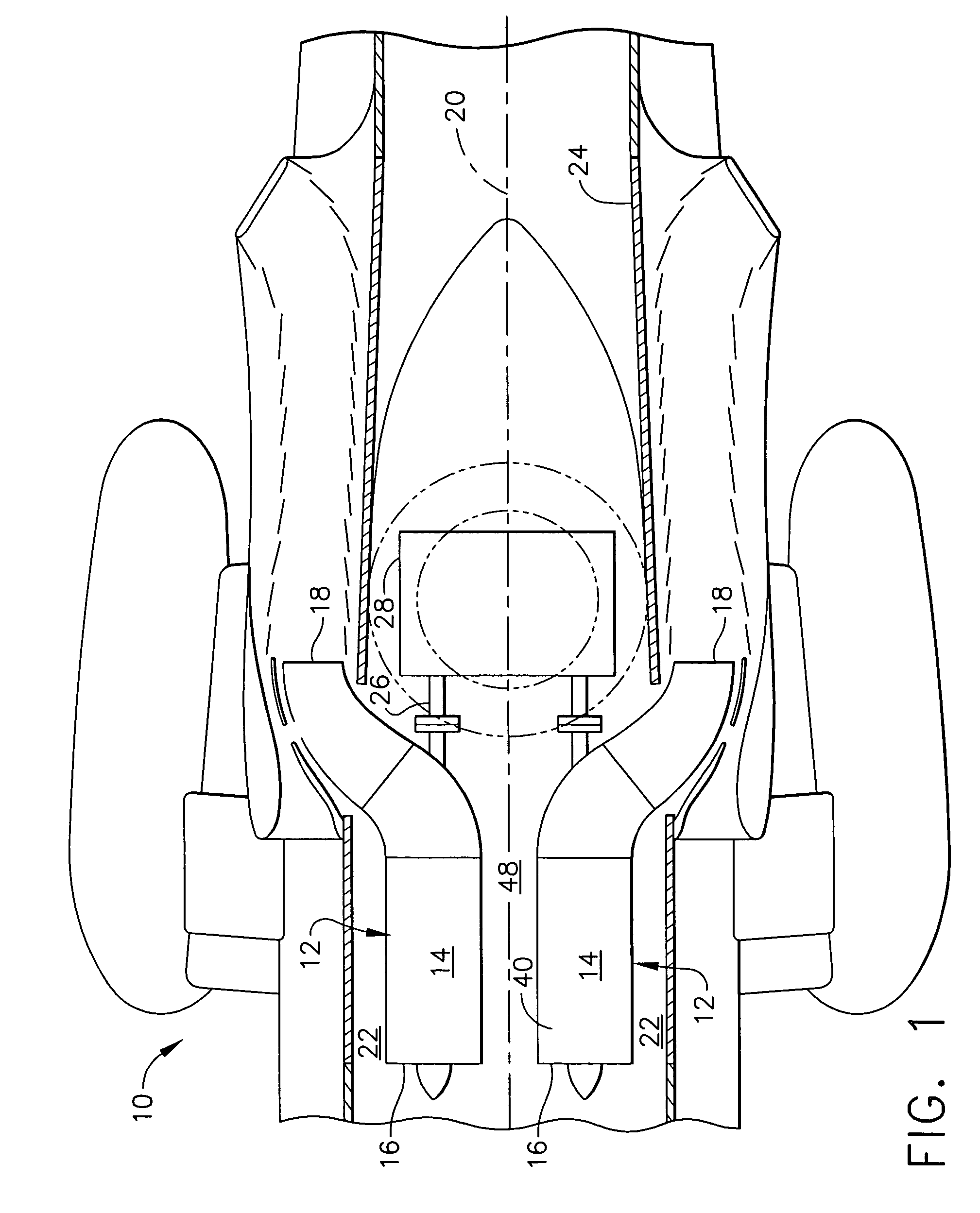
[0016]FIG. 1 is a plan view of a portion of an exemplary helicopter 10 that includes two gas turbine engine assemblies 12. Each gas turbine engine assembly 12 includes a pair of gas turbine engines 14, each of which includes an inlet 16 and an exhaust 18. The gas turbine engines 14 are oriented symmetrically with respect to an axis of symmetry 20 extending axially between the gas turbine engines 14. Moreover, gas turbine engines 14 are mounted within an engine compartment 22 defined by a helicopter fuselage 24. A rear drive shaft 26 extends from each gas turbine engine 14 to a main transmission 28. In other designs, drive shaft 26 may extend out of the front of each engine 14.

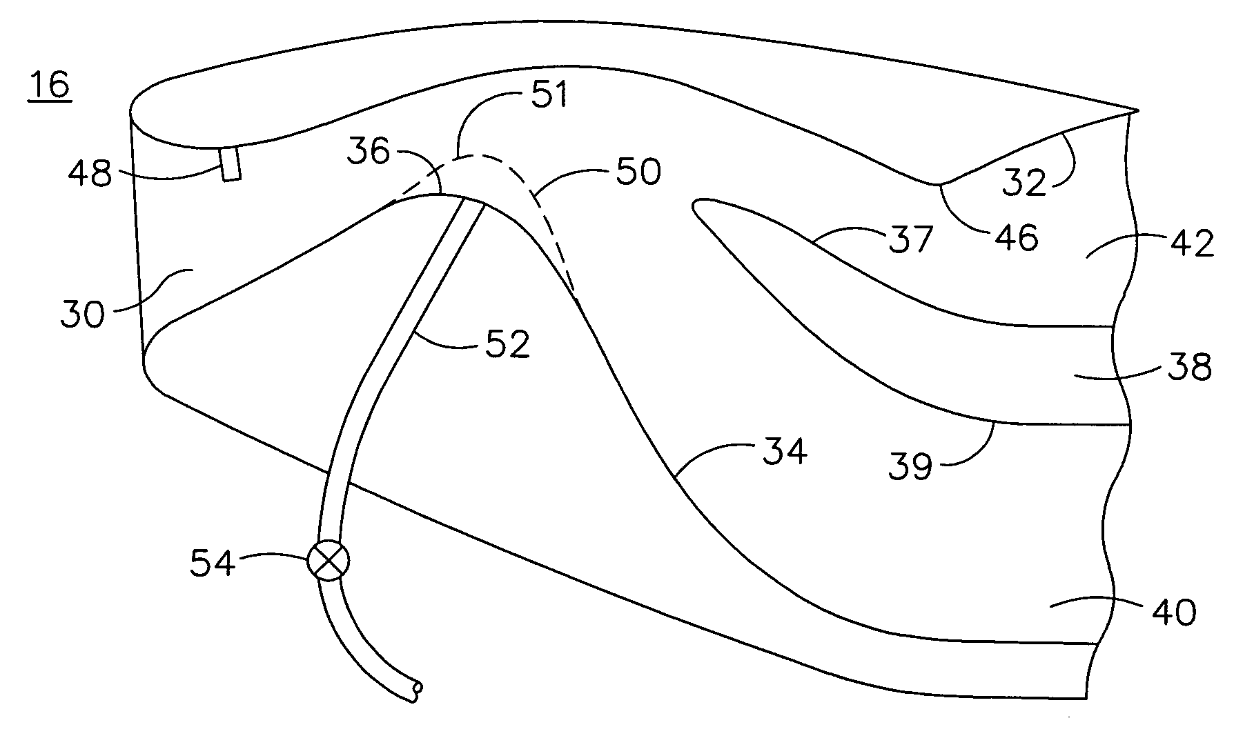
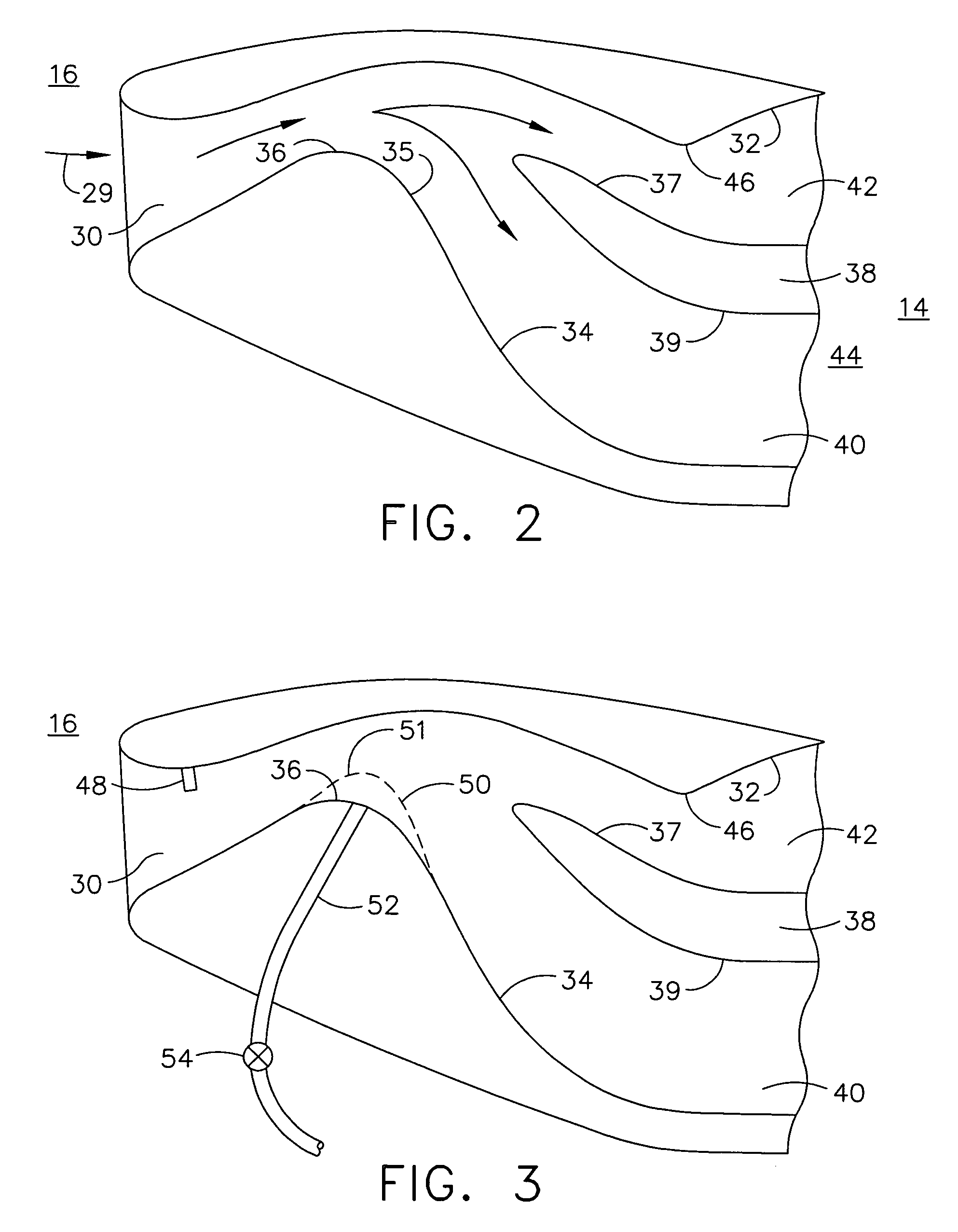
[0017]FIG. 2 is an enlarged cross-sectional view of a portion of gas turbine engine inlet 16. Inlet 16 may be integral with engine 14 or may be separate from engine 14. In the exemplary embodiment, inlet 16 functions as an inertial particle separator (IPS) and includes an entry channel 30 defined by an outer su...


PUM


Abstract

A method for operating a gas turbine engine including a compressor is provided. The method includes defining a predetermined concentration, placing at least one sensor in an inlet of the gas turbine engine, detecting a sand and dust concentration value using the at least one sensor; and deploying a boot to facilitate preventing particles from entering the compressor when the sand and dust concentration value equals or exceeds the predetermined concentration. The boot includes a plurality of fluid exit slots such that clean air is facilitated to be adhered to a flow path surface downstream from the boot.

Description

BACKGROUND OF THE INVENTION[0001]This invention relates generally to gas turbine engines, and more particularly, to adaptive inertial particle separators and methods of use.[0002]Sand and dust ingestion in gas turbine engines may adversely affect engine performance and reliability, and may also increase the frequency of repair and maintenance required for the engines. Because flight readiness depends at least partially on reliably and properly functioning engines, reducing the occurrence of, and / or the effects of, sand and dust ingestion should facilitate enhancing the reliability of the engines.[0003]Various methods are employed to facilitate reducing sand and dust concentrations channeled via the inlet airflow to the engine compressor. For example, known inertial particle separator (IPS) systems perform well in any weather conditions, are highly reliable, are integrated into the engine, but may not provide adequate separation efficiency during severe sand and dust conditions. Iner...

Claims


Application Information

Patent Timeline
Patent Type & Authority Patents(United States)
IPC IPC(8): F02C7/00
CPCF02C7/042F02C7/052F02C7/05
Inventor HIGGINS, TIMOTHY J.
Owner GENERAL ELECTRIC CO
Learn More