Method and system for taxiing an aircraft

a technology for taxiing aircraft and aircraft, applied in the direction of aircraft power plants, machines/engines, gas turbine plants, etc., can solve the problems of increasing the interval between an arrival and a departure, increasing the operating cost of taxiing an aircraft, and increasing the delay

Active Publication Date: 2010-09-28
PRATT & WHITNEY CANADA CORP
View PDF20 Cites 58 Cited by
  • Summary
  • Abstract
  • Description
  • Claims
  • Application Information

AI Technical Summary

Benefits of technology

[0003]In order to mitigate at least some of the above-mentioned problems, it is an object of the present invention to provide an improved method and system allowing an aircraft to taxi under its own power using one or more engines where thrust is generated during taxiing using a propulsor receiving at least a major portion of its power from an electrical motor provided in the corresponding engine.

Problems solved by technology

Even if they are not in the immediate vicinity of aircrafts, passengers and airport personnel must keep away from them due to the noise and the wake created by an operating engine.
This may increase the interval between an arrival and a departure, which can be a significant drawback, especially in the case of aircrafts whose operations involve numerous short stops.
Also, crowed airports may require aircrafts to run engines at idle or at low speeds for a long time between a terminal gate and the runway, or vice-versa.
Since fuel is burned during the operation of the engine, any delay while taxiing an aircraft increases its operating costs.

Method used


Image

  • Method and system for taxiing an aircraft
  • Method and system for taxiing an aircraft
  • Method and system for taxiing an aircraft

Examples


Embodiment Construction

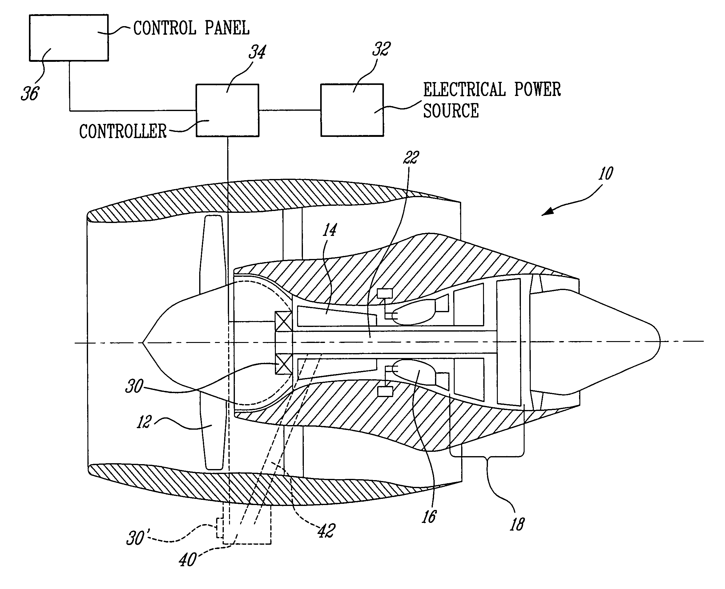
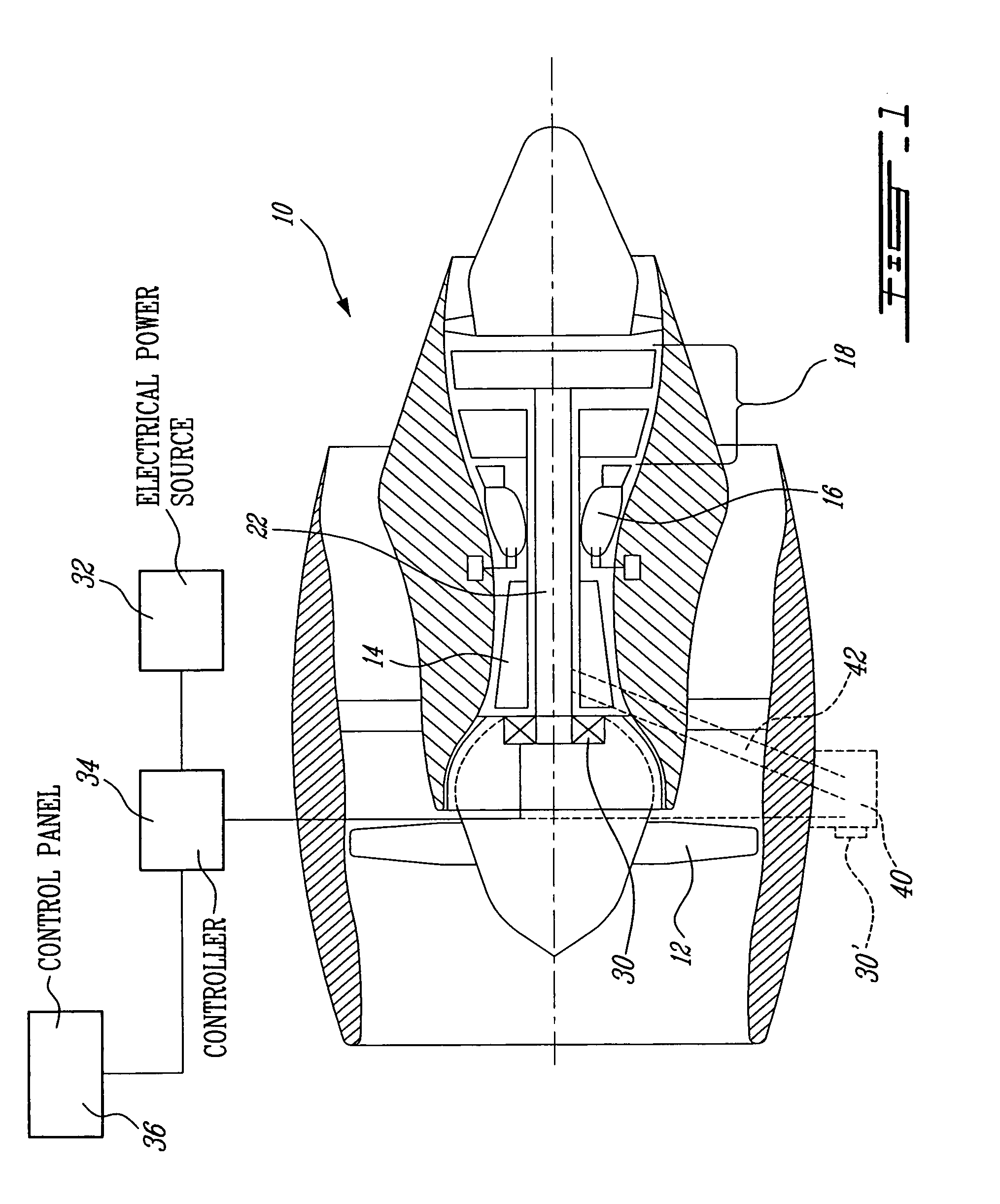
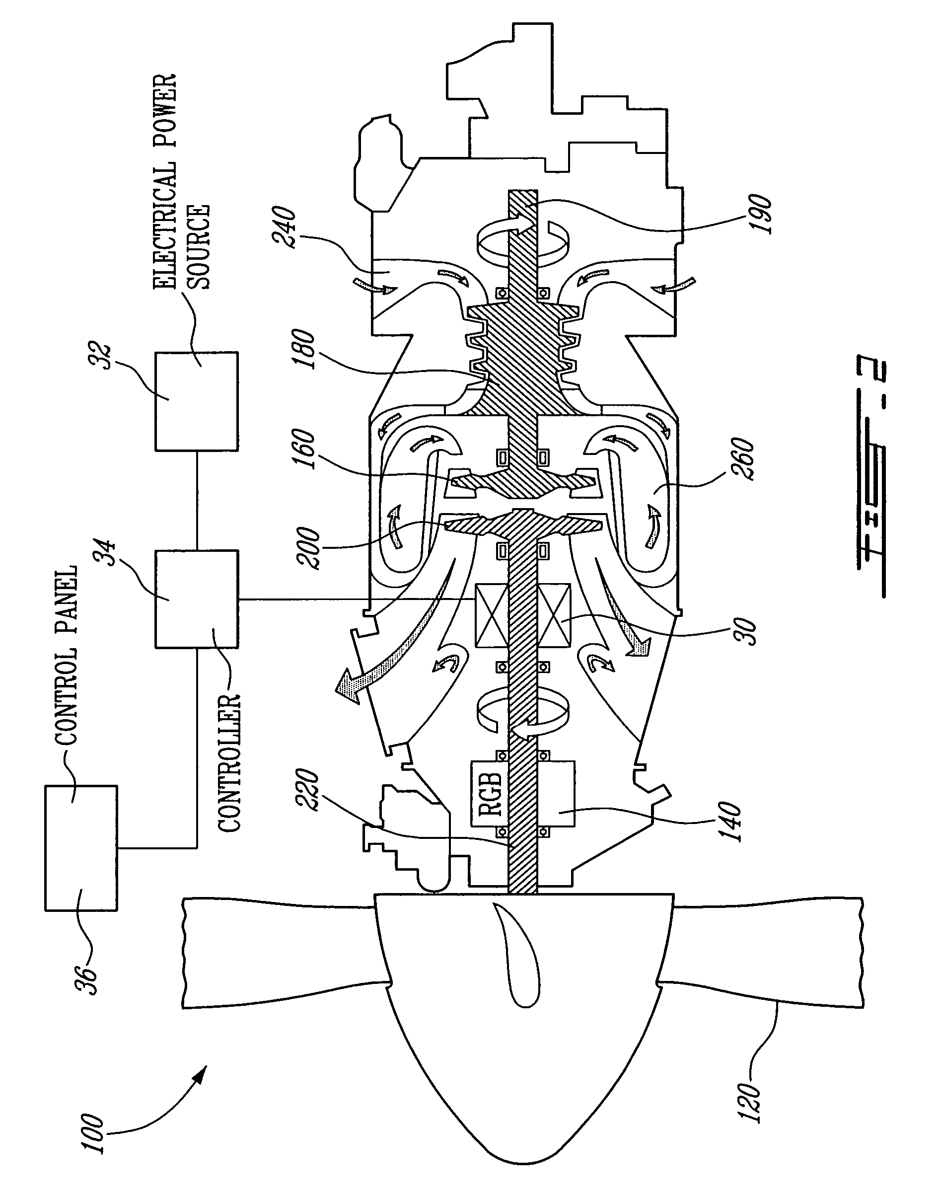
[0012]FIG. 1 illustrates an example of a turbofan 10. This engine 10 comprises in serial flow communication a propulsor, in this case a fan 12, through which ambient air is propelled, a multistage compressor 14 for pressurizing the air, a combustor 16 in which the compressed air is mixed with fuel and ignited for generating an annular stream of hot combustion gases, and a turbine section 18 for extracting energy from the combustion gases. The fan 12, when rotated, generates thrust using the power received through at least one turbine of the turbine section 18.

[0013]FIG. 1 also shows that the engine 10 is provided with an electrical motor 30 coaxially mounted and in a torque-driving engagement on the shaft 22 of the low pressure spool to which the fan 12 is connected. The electrical motor 30 is designed to be sufficiently powerful to drive the fan 12 in order to taxi the aircraft without using fuel in the engine 10 or using a significantly reduced amount of fuel. Electricity is sent ...


PUM


Abstract

The system is used for taxiing an aircraft and comprises at least one multi-spool gas turbine engine, the engine having an electrical motor in a torque-driving engagement with a low pressure spool of the engine. The low pressure spool has a propulsor connected thereon to generate thrust when rotated. A controller is connected to the electrical motor and an electrical power source to control an amount of electrical power provided from the power source to the electrical motor so as to drive the propulsor and cause at least a major portion of the thrust to be generated by the propulsor for moving the aircraft during taxiing.

Description

TECHNICAL FIELD[0001]The invention relates generally to a method and a system for taxiing an aircraft having at least one gas turbine engine.BACKGROUND OF THE ART[0002]In many airports, especially small airports, some passengers are required to walk outside between a terminal gate and an aircraft. Passengers and airport personnel must be kept at a sufficient distance from any aircraft having a gas turbine engine in operation. Even if they are not in the immediate vicinity of aircrafts, passengers and airport personnel must keep away from them due to the noise and the wake created by an operating engine. This may increase the interval between an arrival and a departure, which can be a significant drawback, especially in the case of aircrafts whose operations involve numerous short stops. Also, crowed airports may require aircrafts to run engines at idle or at low speeds for a long time between a terminal gate and the runway, or vice-versa. Running at least one engine is required to t...

Claims


Application Information

Patent Timeline
Patent Type & Authority Patents(United States)
IPC IPC(8): B64D35/00F02C7/275
CPCF01D15/10F02C7/262F02C7/32F02K5/00F02C7/268F05D2220/76
Inventor DOOLEY, KEVIN ALLANYOUSSEF, NASHED
Owner PRATT & WHITNEY CANADA CORP
Why Eureka
Try Eureka