Pendulum and slide gate vacuum valve

a vacuum valve and plug-in technology, applied in the field of vacuum valves, can solve the problems of inability to ensure uniform force distribution along the entire circumference of the sealing ring, inability to maintain, and easy soiling, etc., and achieves the effect of simple and compact design, easy maintenance, and withstanding high pressure loads

Active Publication Date: 2010-09-28
VAT HLDG AG
View PDF16 Cites 14 Cited by
  • Summary
  • Abstract
  • Description
  • Claims
  • Application Information

AI Technical Summary

Benefits of technology

[0012]It is therefore an object of the invention to solve the problems described above and to provide a valve of the type mentioned at the outset which has a simple and compact design, is easy to maintain and is capable of withstanding high pressure loads—optionally active on both sides.SUMMARY OF THE INVENTION
[0017]By means of the drive or by means of an additional drive, the perpendicular distance between the valve plate and the first valve seat, starting from the intermediate position, can be reduced so that, in a closed position, the flow path is closed essentially gastight by an axially sealing contact between the first sealing ring and the first valve seat. This is effected in particular by a perpendicular movement of the valve plate with its closing side on to the valve seat. In order to avoid shear forces when the first sealing ring is pressed onto the valve seat, this movement should be effected as far as possible linearly and perpendicularly to the valve seat. Pressing on by means of a pivot movement is also possible, the pivot axis being a distance away from the opening so that a quasi-linear movement on the valve plate takes place during pressing on. Alternatively or additionally, it is possible to reduce the distance between the valve plate and the first valve seat by moving the valve seat in the direction toward the closing side of the valve plate. In this embodiment, a movement of the valve plate perpendicularly to the valve seat can be omitted. Different drive variants for achieving the at least two stage movement described are known from the prior art and are not explained further. It is also possible to combine the two movements by fading from the parallel movement to the perpendicular movement, and / or vice versa. In this case, the intermediate position is reached when the parallel movement of the valve plate stops or is so small that shear forces are avoided when the first sealing ring is pressed onto the valve seat.
[0029]In a further development of the invention, the valve plate comprises resilient means, in particular at least one spring, which are arranged in such a way and act between the support part and the sealing part in such a way that the sealing part is pressed within its range of movement in the starting position in the direction of the first valve seat and the closing side and, in the closed position with relative pressure equality at the valve, rests directly or indirectly on the valve housing, in particular on the first valve seat or a lateral surface of the groove. If there is a change from the state of pressure equality to reduced pressure or excess pressure on the closing side, the sealing part already resting on the valve housing remains unmoved and an excessive mechanical load is avoided.
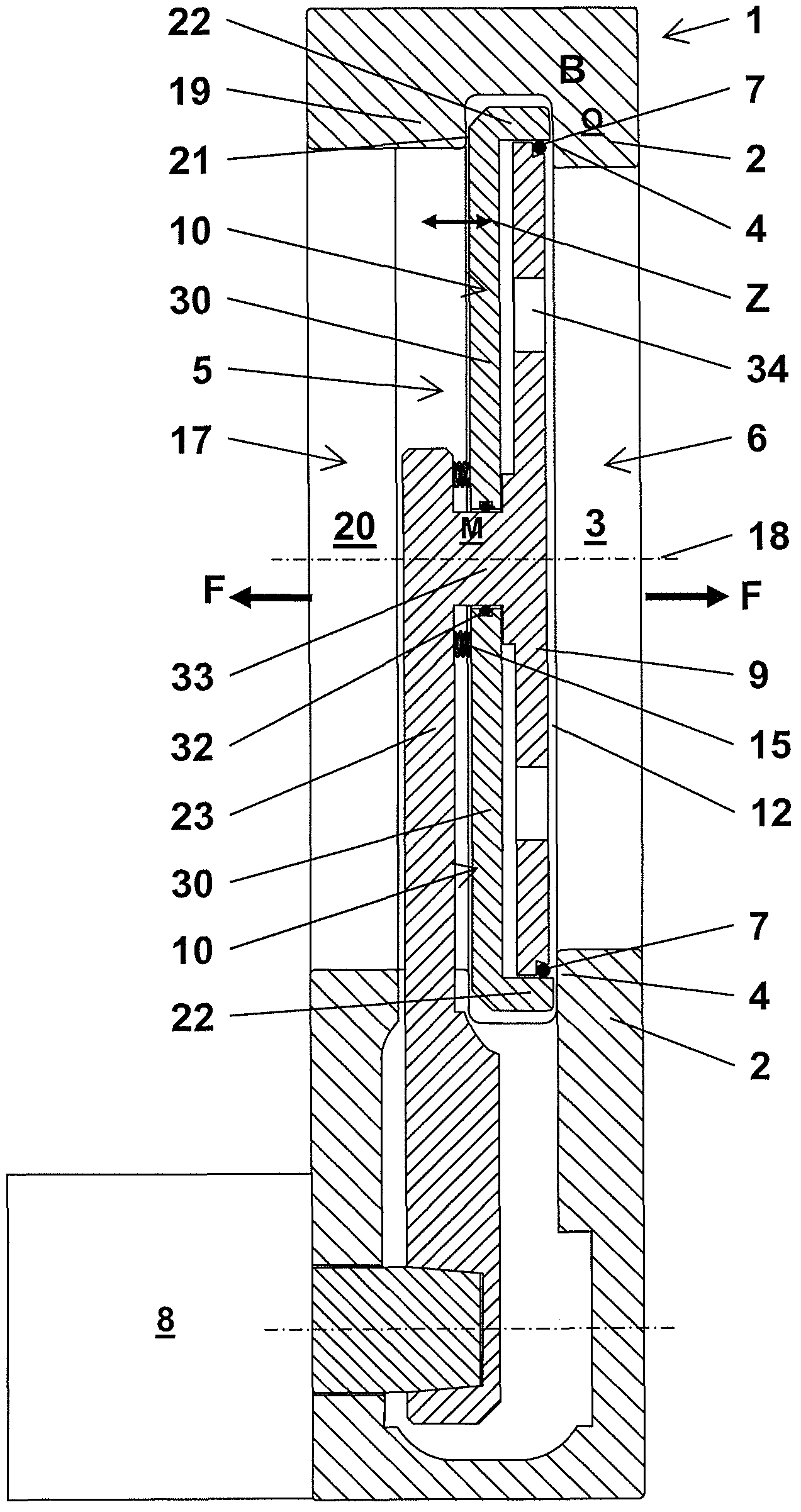
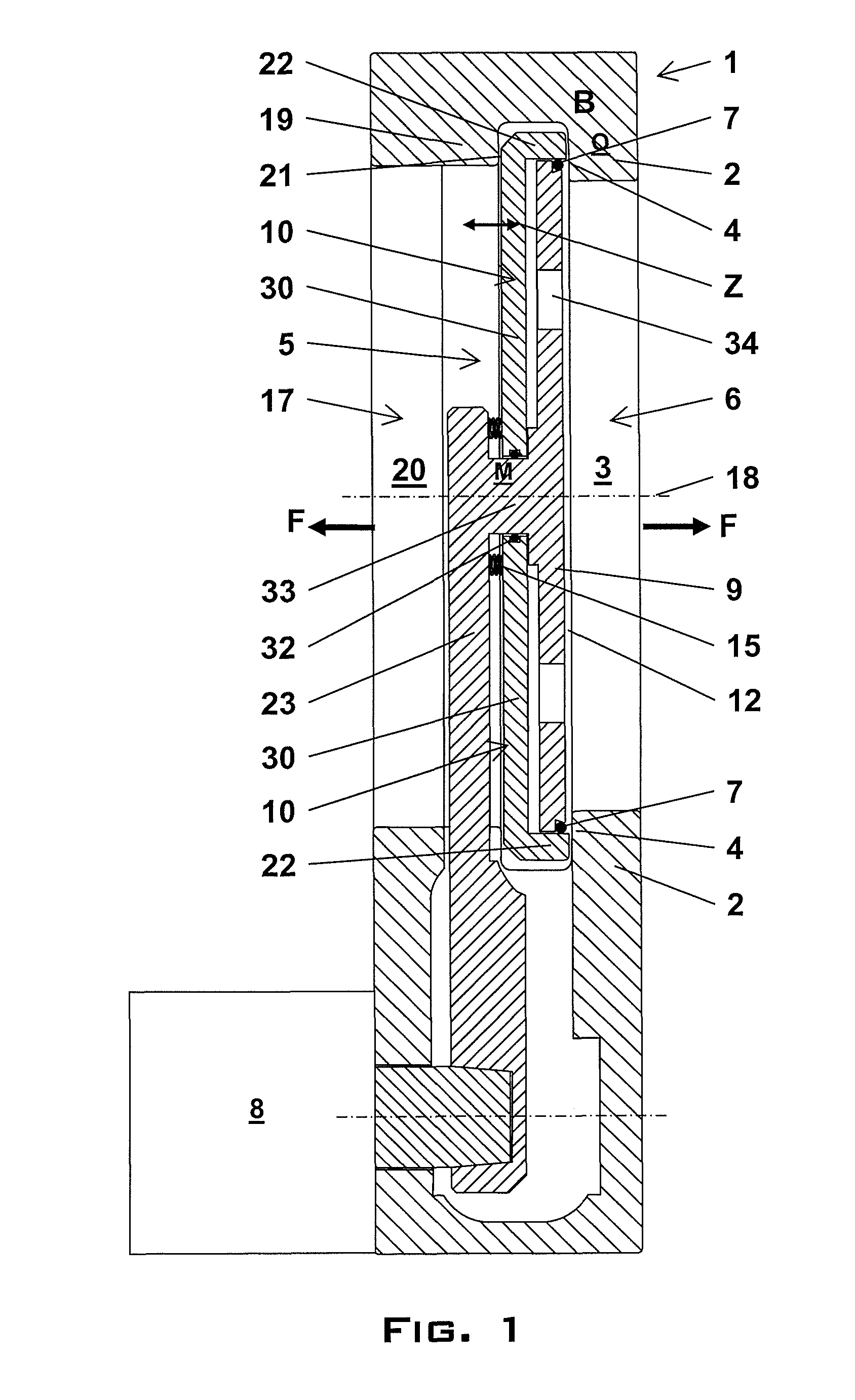
[0030]In a further, advantageous embodiment, the valve housing additionally has, in an essentially parallel opposite position a distance away relative to the first wall and the first opening, a second wall having a second opening for the flow path and a second valve seat surrounding the second opening. The valve plate is pivotable or displaceable between the first opening and the second opening, and in the intermediate position and in the closed position, the valve plate is pivoted or displaced between the first opening and the second opening. The driving of the valve plate and the opening and closing of the first opening are effected as described above. In the closed position of the valve, the second opening is present on that side of the valve plate which is opposite the closing side. In this embodiment, the sealing part is formed in such a way that, in the closed position with a relative excess pressure on the closing side of the valve plate, the sealing part is supported perpendicularly, essentially decoupled from the support part, on the second valve seat. For this purpose or in general, the sealing part has, for example, an outer annular section and an inner plate-like section. The outer annular section at least partially encloses the support part, the first sealing ring and the inner plate-like section. The outer annular section, in particular being hollow-cylindrical, extends parallel, in particular coaxially, to the central axis of the first opening, especially perpendicularly between the first valve seat and the second valve seat. By means of outer annular section, support on the second valve seat occurs in the case of relative excess pressure. Consequently, in the closed position, the possible relative range of movement of the sealing part is limited on one side of the valve plate by support of the front area of the annular section on the first valve seat and on the other side of the valve plate by support of the back area of the annular section on the second valve seat. As a result of this, the valve has a high load capacity on both sides. A transition from reduced pressure to excess pressure and vice versa results in a change of the support areas of the sealing part without the contact pressure of the support part with its first sealing ring on the first valve seat being influenced thereby. Thus, the valve according to the invention has a high load capacity on both sides without considerable loading of the drive or of a sealing area.
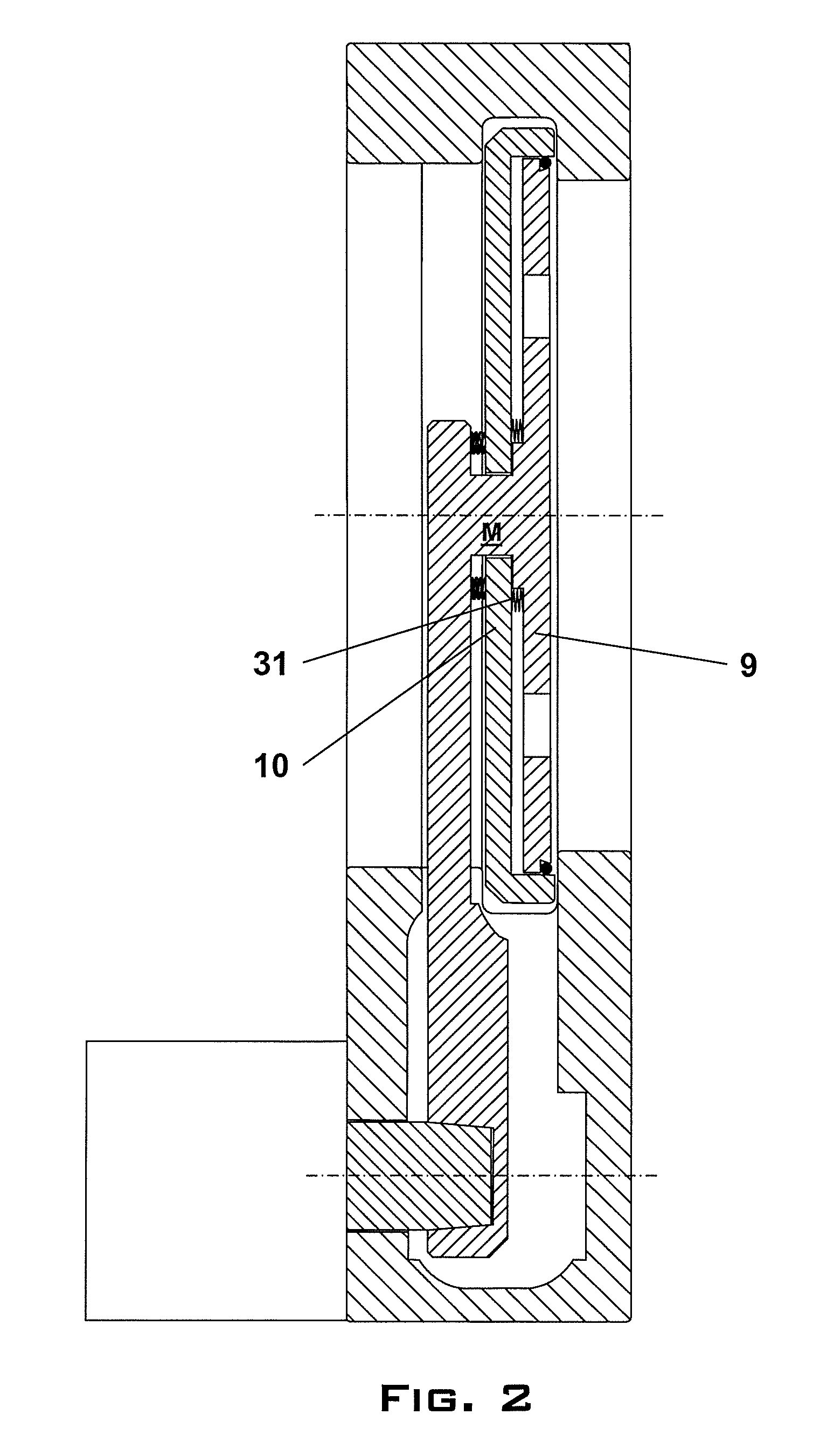
[0032]The sealing part is connected in an essentially gastight way to the support part in the central region by means of at least one second sealing ring and / or at least one bellows. Any other kind of gastight and, in particular, flexible connection allowing the movement between the support part and the sealing part is possible.
[0034]A similar effect of supporting the sealing part can also be achieved by an inner lateral groove in the valve housing, which groove is formed and arranged in such a way that at least a partial section of the sealing part, in particular at least one outer lateral collar, arranged on the sealing part, projects into the lateral groove in the closed position and, in particular, in the intermediate position, and in case of the pressure difference at the valve plate, the sealing part is supported on the valve housing, on a lateral area—in particular alternately both opposite lateral areas—of the lateral groove. Further developments for supporting the sealing part on the valve housing are of course possible.

Problems solved by technology

Particularly in the case of large pressure variations or change from reduced pressure (relative negative pressure) to excess pressure (relative positive pressure), or vice versa, a uniform force distribution along the entire circumference of the sealing ring cannot, however, always be ensured.
The design of the vacuum valves described is relatively complex especially owing to the necessity of using a bellows or a plurality of large sealing rings for sealing the first plate section from the second plate section and from the valve seat and is disadvantageous to maintain and susceptible to soiling.
Since sealing rings in the outer region of the valve plate and having a relatively large diameter are susceptible and sensitive wearing parts, the use of a plurality of large sealing rings is disadvantageous.
A further disadvantage of such valves having an actively adjustable valve ring is the relatively complicated and bulky design of the valve, the necessity of a complex control of the contact pressure and the presence of a plurality of moving parts in the flow channel, which complicate maintenance and cleaning of the valves.
In particular valves with an actively adjustable valve ring or valve plate sections meet this requirement only to an insufficient extent for numerous applications.

Method used


Image

  • Pendulum and slide gate vacuum valve
  • Pendulum and slide gate vacuum valve
  • Pendulum and slide gate vacuum valve

Examples


Embodiment Construction

[0049]FIG. 1 shows a possible embodiment of the valve according to the invention in the form of a pendulum valve. In a valve housing 1 having two walls opposite one another a distance apart, a first wall 2 and a second wall 19, two openings likewise opposite one another and having a round cross-section, a first opening 3 and a second opening 20, are formed, which openings form a flow path F leading through the valve for a gas or fluid. The two openings 3 and 20 have a common opening axis, the central axis 18 of the first opening 3. A first valve seat 4 which surrounds the first opening 3 and is formed by a flat, defined area of the first wall 2 and through whose plane the central axis 18 passes perpendicularly is formed on the inner areas of the first wall 2. Also present on the inner area of the second wall 19, parallel to the first valve seat 4, is a second valve seat 21. A drive 8 which is connected by means of an arm 23 to a valve plate 5 is arranged on the valve housing 1. The ...


PUM


Abstract

The invention relates to a valve, in particular a pendulum or slide gate valve, for essentially gastight closing of a flow path (F). The valve includes a valve housing (1) having a first wall (2) which has a first opening (3) and a first valve seat (4), a valve plate (5) having a closing side (6) with a first sealing ring (7) and at least one drive (8). By action of the drive (8), the valve plate (5) is pivotable or displaceable from an opened position (A) essentially parallel to the first valve seat (4), and the perpendicular distance between the valve plate (5), and the first valve seat (4) can be reduced so that, in the closed position (C), the flow path (F) is closed essentially gastight by an axially sealing contact between the first sealing ring (7) and the first valve seat (4). The valve plate (5) includes support part (9), which is connected to the drive (8) and fixes the first sealing ring (7) in the perpendicular direction to the first valve seat (4), and a sealing part (10) which has an inner circumferential area (11) and which is mounted so as to be movable relative to the support part (9) in a direction (Z) essentially perpendicular to the first valve seat (4). The inner circumferential area (11) encloses the first sealing ring (7) in an essentially gastight way with an inner seal. Thus, in the closed position (C), a pressure difference at the valve plate (5) acts essentially on the sealing part (10) so that sealing part (10), decoupled from the support part (9), is supported perpendicularly on a section of the valve housing (1), in particular the first valve seat (4) or a lateral groove (27).

Description

CROSS-REFERENCE TO RELATED APPLICATIONS[0001]This application is a continuation-in-part of U.S. application Ser. No. 11 / 588,354, filed Oct. 27, 2006, which is a continuation-in-part of U.S. application Ser. No. 11 / 311,434, filed Dec. 20, 2005.TECHNICAL FIELD OF THE INVENTION[0002]The invention relates to a vacuum valve for essentially gastight closing of a flow path by swivelling or moving a valve plate over an opening and pressing the valve plate onto a valve seat surrounding the opening. Such valves are used in particular in vacuum technology and are referred to in particular as pendulum valves or slide gate valves.DESCRIPTION OF THE PRIOR ART[0003]Valves of the type mentioned at the outset are known in different embodiments from the prior art and are used in particular in the area of IC and semiconductor manufacture, which must take place in a protected atmosphere, as far as possible without the presence of contaminating particles. Pendulum valves serve, for example, for controll...

Claims


Application Information

Patent Timeline
Patent Type & Authority Patents(United States)
IPC IPC(8): F16K1/16
CPCF16K3/10F16K51/02
Inventor GEISER, FRIEDRICH
Owner VAT HLDG AG
Why Eureka
Try Eureka