Monolithic shell for an optical electrical device

Active Publication Date: 2010-09-28
II VI DELAWARE INC
View PDF14 Cites 19 Cited by
  • Summary
  • Abstract
  • Description
  • Claims
  • Application Information

AI Technical Summary

Problems solved by technology

In addition, the top portion and the bottom portion are configured such that the top portion is not separable from the bottom portion.

Method used


Image

  • Monolithic shell for an optical electrical device
  • Monolithic shell for an optical electrical device
  • Monolithic shell for an optical electrical device

Examples


example embodiment

[0042 Implementing a Monolithic, One Piece Shell

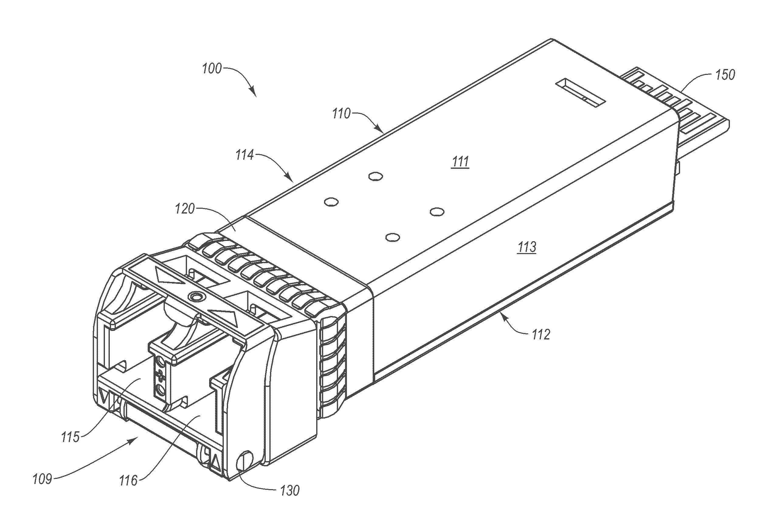
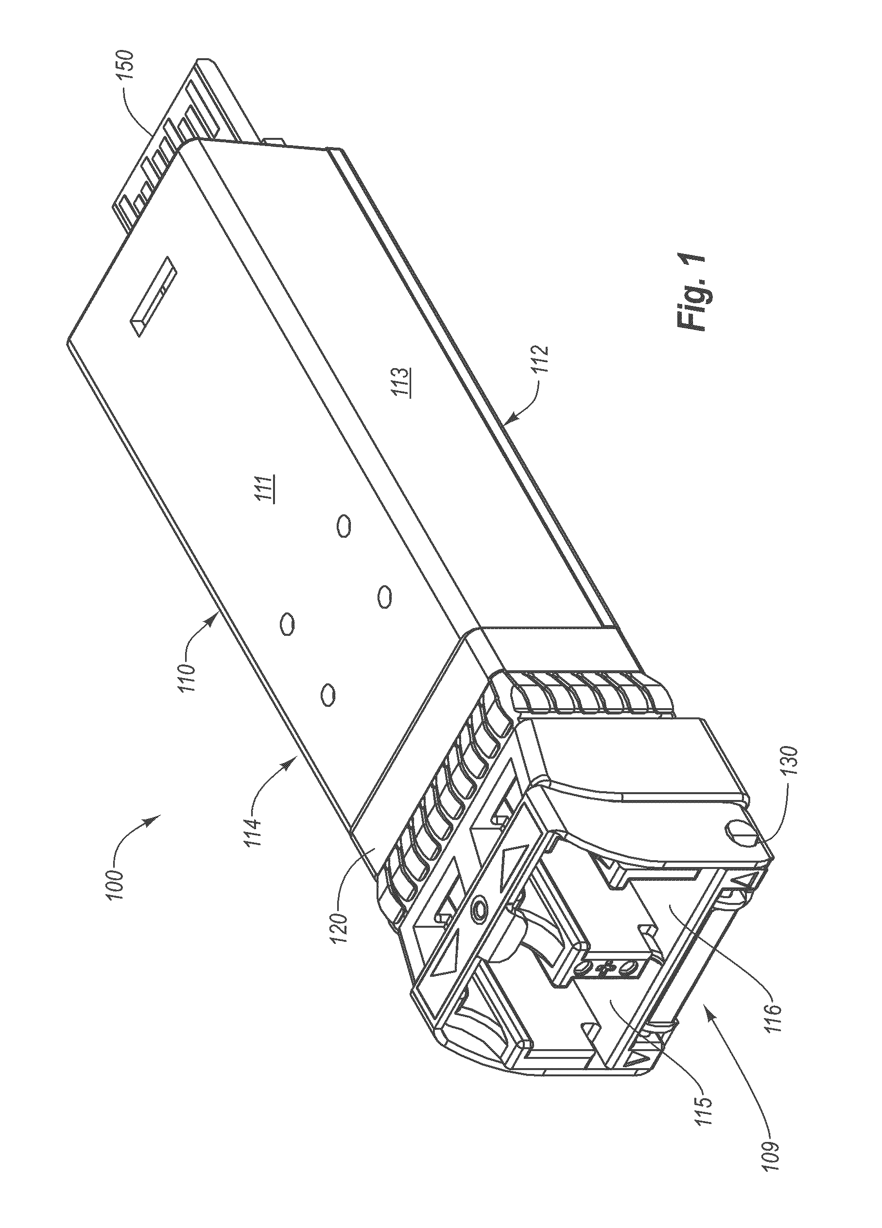
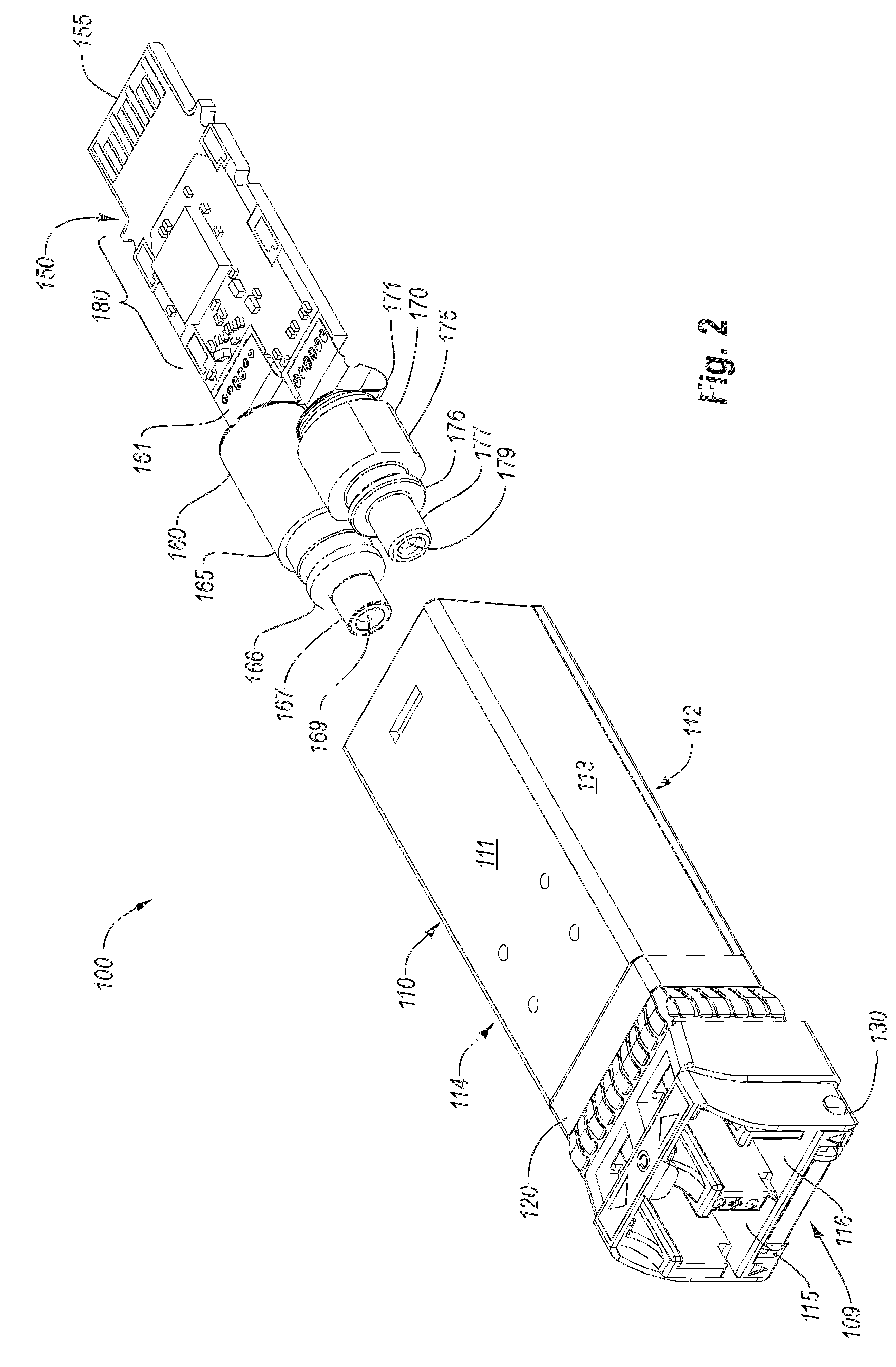
[0043]Reference is now made to FIGS. 4A-4C, which illustrate a specific embodiment of an optoelectronic transceiver module 100 that implements a monolithic, one piece shell. As illustrated, FIG. 4A includes a monolithic, one piece shell 110 as previously described. FIG. 4A also shows a PCB carrier 200 that may be used with monolithic, one piece shell 110.

[0044]As shown, PCB carrier 200 includes a bottom portion 210, a top portion 220, and an end portion 230. Note that end portion 230 includes a clip 240 that is configured to help secure PCB carrier 200 with monolithic, one piece shell 110. In one embodiment, PCB carrier 200 may be made of plastic, although other suitable materials may also be used. PCB carrier is configured to enclose PCB 150 and the transceiver electronics, TOSA, and ROSA implemented thereon.

[0045]In one embodiment, PCB 150 is placed onto bottom portion 210. Top portion 220 is then rotated into place on top of PCB 150...


PUM


Abstract

An optoelectronic transceiver module. The optoelectronic module is a monolithic, one-piece module shell that includes a top portion, a bottom portion, a first side portion, a second side portion, and a front portion. The top portion, bottom portion, first side portion, second side portion and the front portion define a cavity configured to enclose electro-optical circuitry. In addition, the top portion and the bottom portion are configured such that the top portion is not separable from the bottom portion. Further, the front portion defines at least one of an optical transmit port or an optical receive port.

Description

CROSS-REFERENCE TO RELATED APPLICATIONS[0001]This application claims the benefit of U.S. Provisional Application No. 60 / 977,941, filed Oct. 5, 2007, which is incorporated herein by reference in its entirety.BACKGROUND[0002]Electronic modules, such as electronic or optoelectronic transceiver or transponder modules, are increasingly used in electronic and optoelectronic communication. Some electronic modules can be plugged into a variety of host networking equipment. Multi-Source Agreements (“MSAs”), such as the SFF MSA, the SFP MSA, XENPAK MSA, X2 MSA and the SFP+ (IPF) MSA specify, among other things, package dimensions for electronic modules. Conformity with an MSA allows an electronic module to be plugged into host equipment designed in compliance with the MSA. Electronic modules typically communicate with a printed circuit board of a host device by transmitting electrical signals to the printed circuit board and receiving electrical signals from the printed circuit board. These e...

Claims


Application Information

Patent Timeline
Patent Type & Authority Patents(United States)
IPC IPC(8): G02B6/36
CPCG02B6/4201H05K9/0047H05K9/0049H05K9/0058
Inventor MOORE, JOSHUASASSER, GARY DEANLIGHT, GRETA
Owner II VI DELAWARE INC
Why Eureka
Try Eureka