
Signal line connector structure of computer system

a computer system and connector technology, applied in the direction of connection, electrical apparatus, coupling device connection, etc., can solve the problems of high manufacturing difficulty, short circuit, increased defective rate, etc., to improve the convenience of assembly process, stable and convenient assembling process, and wide application rang

Inactive Publication Date: 2010-09-28
HWANG MAO LIN
View PDF3 Cites 32 Cited by
  • Summary
  • Abstract
  • Description
  • Claims
  • Application Information

AI Technical Summary

Benefits of technology

[0007]Therefore, it is a primary objective of the present invention to overcome the aforementioned shortcoming and deficiency of the prior art by providing a signal line connector structure of computer system, and the improved connector structure is simple, easy-to-assemble, easy-to-solder, stable, convenient and highly applicable.
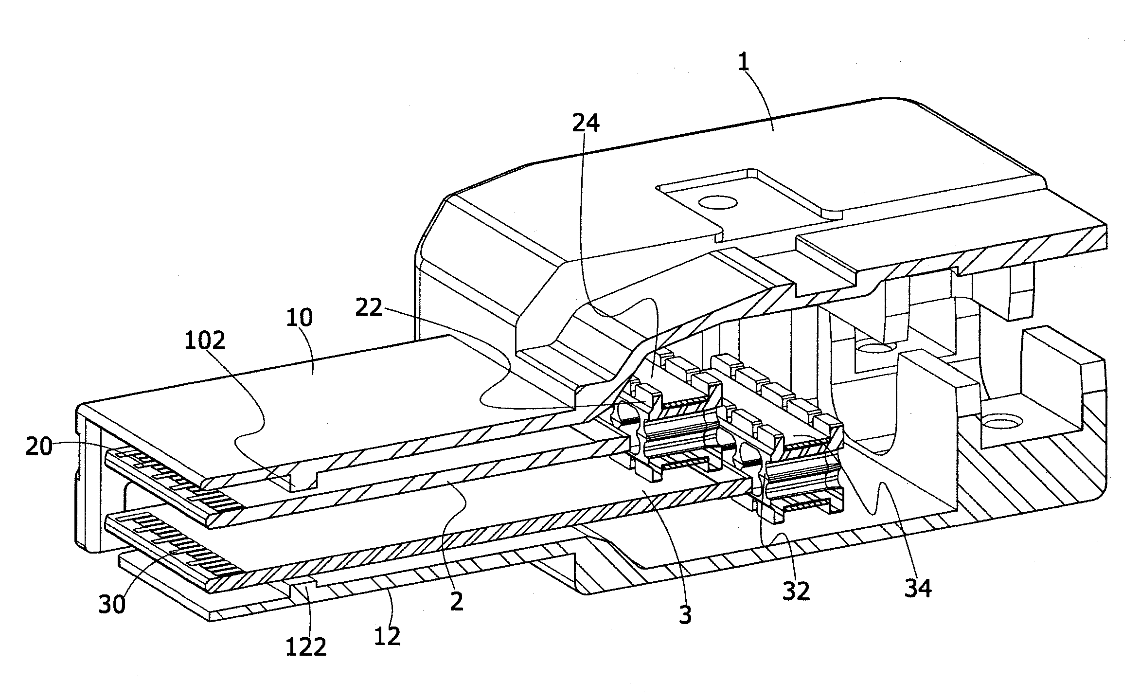
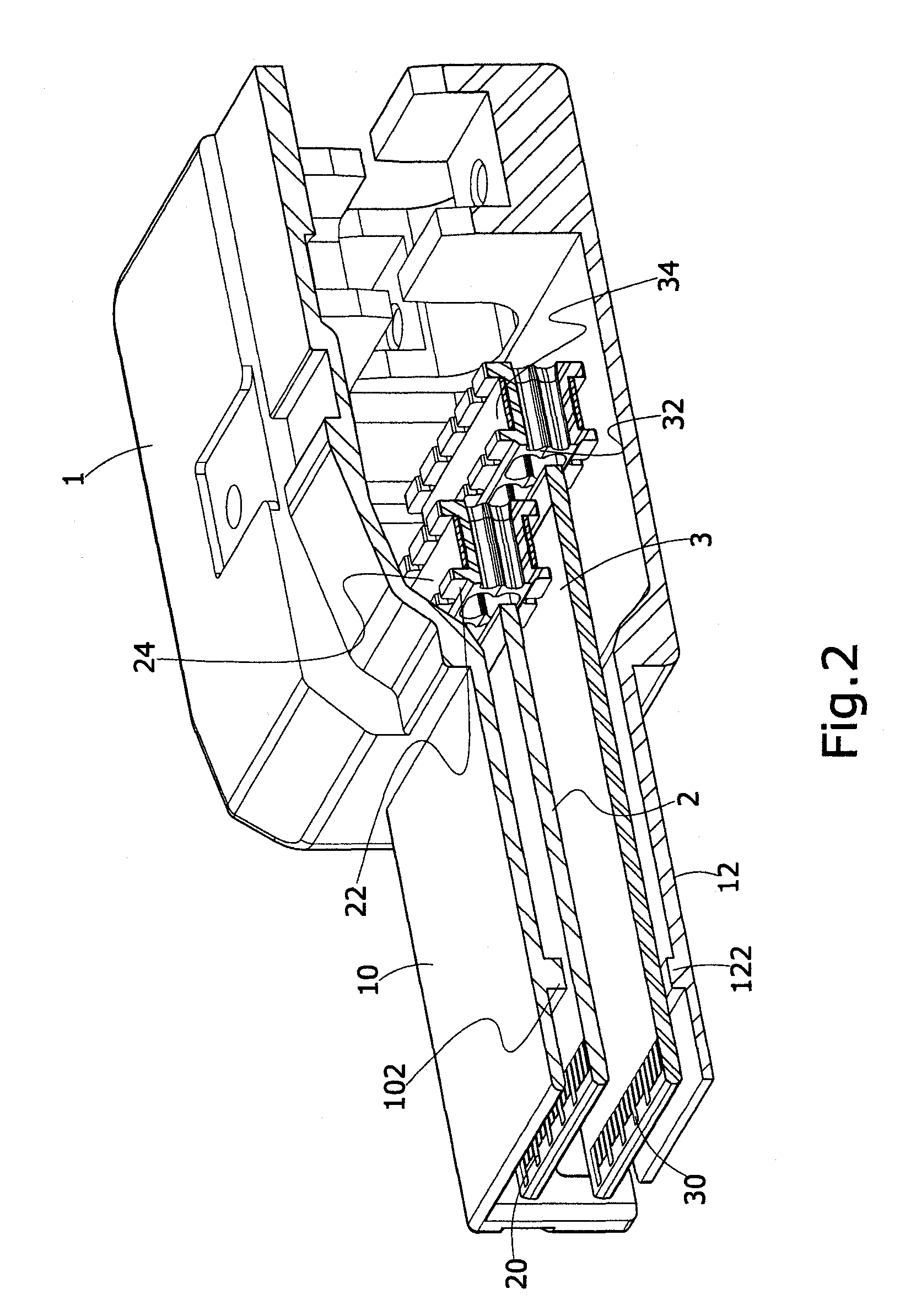
[0009]In the present invention, the casing is formed integrally by a plastic injection molding process or a metal die casting process. To enhance the convenience of the assembling process, the first wire clamping module and the second wire clamping module are formed respectively and symmetrically by two separate plastic clamping plates, and each plastic clamping plate includes a plurality of wire slots penetrated through the plastic plates, and a plurality of flanges corresponding to the signal lines for disposing a plurality of clamp openings of the signal lines respectively. The first grounding clamp module and the second grounding clamp module are formed respectively and symmetrically by two identical metal clamps, and each metal clamp includes a fork frame and a latch hole disposed on a side of the metal clamp, and a latch plate corresponding to the latch hole and disposed on another side of the metal clamp, such that the fork frames can be used for clamping the first circuit board and the second circuit board respectively.
[0010]The present invention is characterized in that the wire clamping module and the grounding clamp module are provided for a more stable and convenient assembling process. In the meantime, the casing contains two connecting modules at the same time, so that the invention can provide a wider scope of applicability.

Problems solved by technology

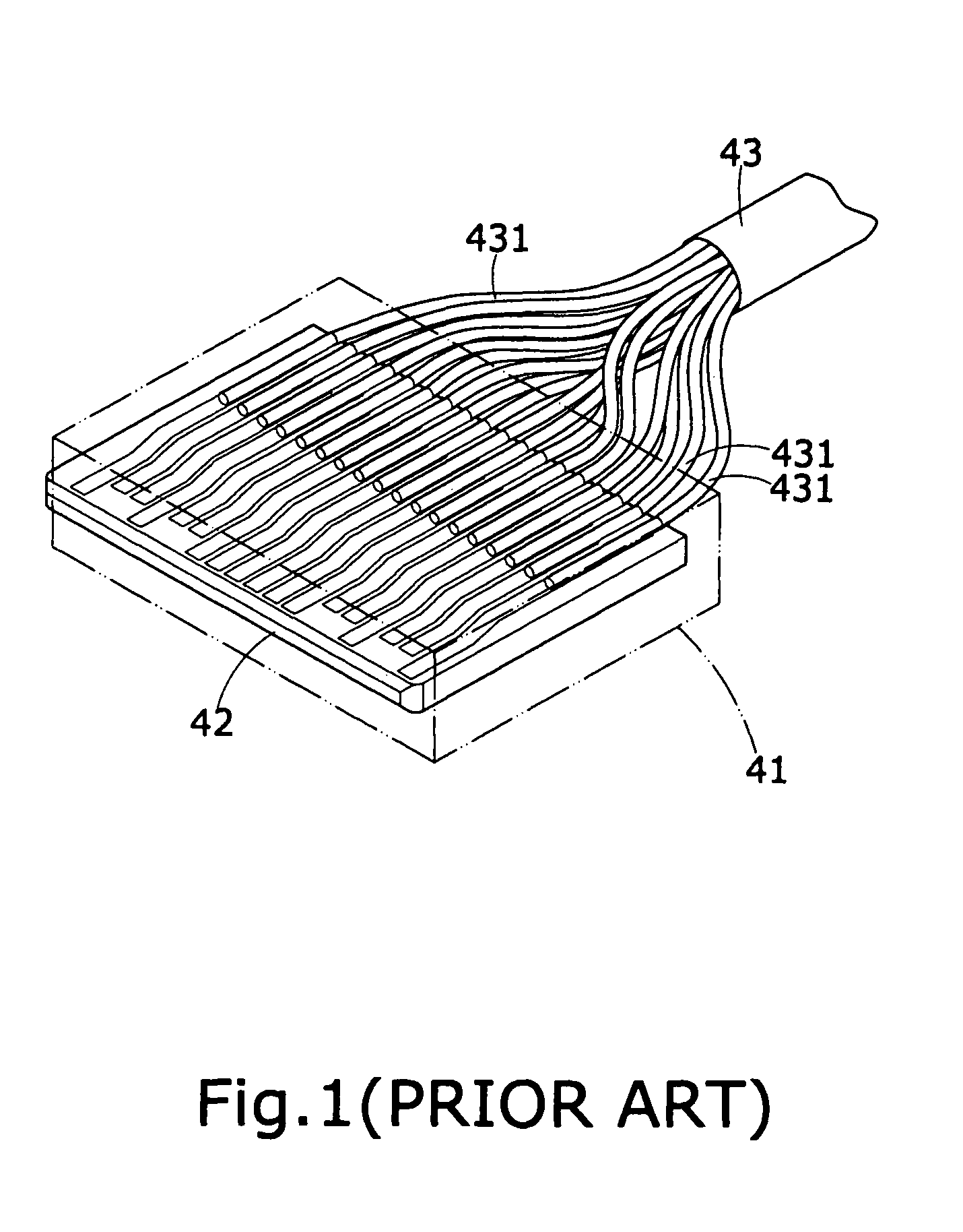
As described above, the flat cable generally has at least 26 pins, and thus an electric wire having more than 20 pins is soldered to a circuit board 42 having a very limited width will become too dense, involve a high level of difficulty for the manufacture, and result in short circuits.
Furthermore, when the cable 43 and the circuit board 42 of the conventional flat cable are connected, each electric wire is not fixed in position, such that wire ends at the soldered positions will be in disorder, and will make the wire peeling and soldering processes difficult or will give rise to an increased defective rate.
Furthermore, the casing 41 of the conventional connector is formed by the molding process in a production line directly, so that the defective products cannot be reworked easily and result in unnecessary wastes.

Method used


Image

  • Signal line connector structure of computer system
  • Signal line connector structure of computer system
  • Signal line connector structure of computer system

Examples


Embodiment Construction

[0016]The technical characteristics of the present invention will become apparent with the detailed description of the preferred embodiments and the illustration of the related drawings.

[0017]With reference to FIGS. 2 to 4 for a perspective view, a cross-sectional view and an exploded view of a signal line connector structure of a computer system in accordance with a preferred embodiment of the present invention respectively, the signal line connector structure comprises a casing 1, a first connecting module 2 and a second connecting module 3. The casing 1 comprises an upper casing 10 and a lower casing 12. The first connecting module 2 comprises a first circuit board 20, a first wire clamping module 22 and a first grounding clamp module 24, and the second connecting module 3 comprises a second circuit board 30, a second wire clamping module 32 and a second grounding clamp module 34.

[0018]The signal line connector structure of a computer system in accordance with the present inventi...


PUM


Abstract

A signal line connector structure of a computer system includes a casing, a first connecting module and a second connecting module. The casing consists of an upper casing and a lower casing. The upper casing includes a first positioning block having a first stop side, and the lower casing includes a second positioning block having a second stop side. The first connecting module and the second connecting module are installed in the casing and abutted and fixed by the first positioning block and the second positioning block respectively to enhance the stability and convenience of the connection. In addition, two connecting modules are used for improving the applicability.

Description

BACKGROUND OF THE INVENTION[0001]1. Field of the Invention[0002]The present invention relates to a connector, and more particularly to an improved signal line connector structure of a computer system.[0003]2. Description of the Related Art[0004]In general, hard disks available in the market are divided into traditional IDE hard disks, SCSI hard disks, and new-generation SATA and SAS hard disks. For the hard disks of different specifications, different connectors and flat cables are required. For example, the connector for the IDE hard disk comes with a general flat cable structure. Since the performance and stability of the hard disks are enhanced increasingly, therefore some traditional specifications are no longer used anymore. For example, the IDE hard disks are replaced by the SATA II hard disks and the SCSI hard disks are replaced by the SAS hard disks gradually.[0005]For the SAS hard disks, a signal connecting wire is generally a circular cable connected with a connector to fo...

Claims


Application Information

Patent Timeline
Patent Type & Authority Patents(United States)
IPC IPC(8): H01R12/24
CPCH01R9/032H01R13/65802H01R13/6658H01R13/5825H01R13/65912
Inventor HWANG, MAO-LIN
Owner HWANG MAO LIN
Learn More