Power supply and stabilizer

a technology of power supply and stabilizer, which is applied in the direction of measurement devices, instruments, and testing of the marginal circuit, can solve the problems of the power supply apparatus described above, but the difficulty of stabilizing the power supply voltag

Inactive Publication Date: 2010-09-28
ADVANTEST CORP
View PDF9 Cites 2 Cited by
  • Summary
  • Abstract
  • Description
  • Claims
  • Application Information

AI Technical Summary

Problems solved by technology

The power supply apparatuses described above, however, have difficulty stabilizing the power supply voltage if the decrease in the power supply current supplied to the electronic device is accompanied by an increase in the power supply voltage.

Method used


Image

  • Power supply and stabilizer
  • Power supply and stabilizer
  • Power supply and stabilizer

Examples


Embodiment Construction

[0021]Hereinafter, some embodiments of the present invention will be described. The embodiments do not limit the invention according to the claims, and all the combinations of the features described in the embodiments are not necessarily essential to means provided by aspects of the invention.

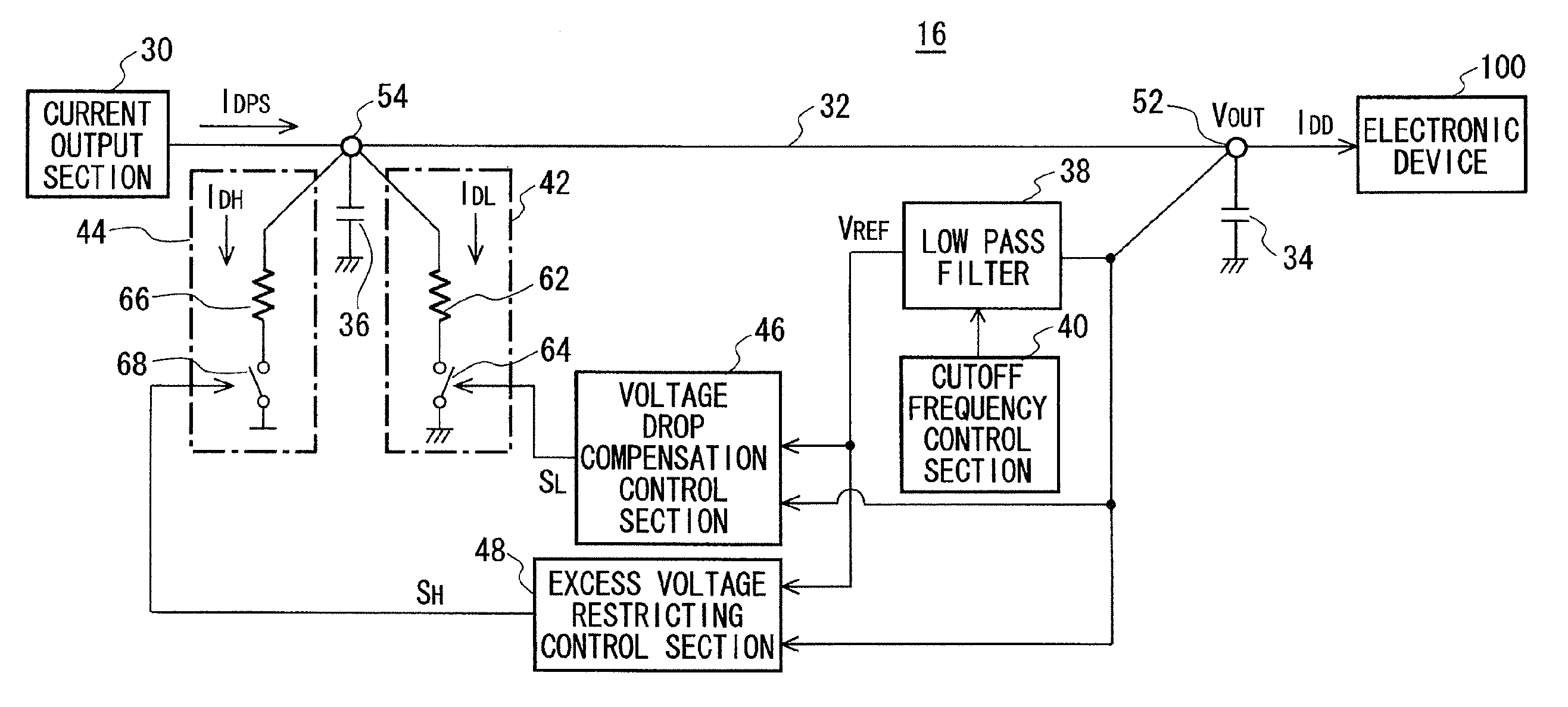
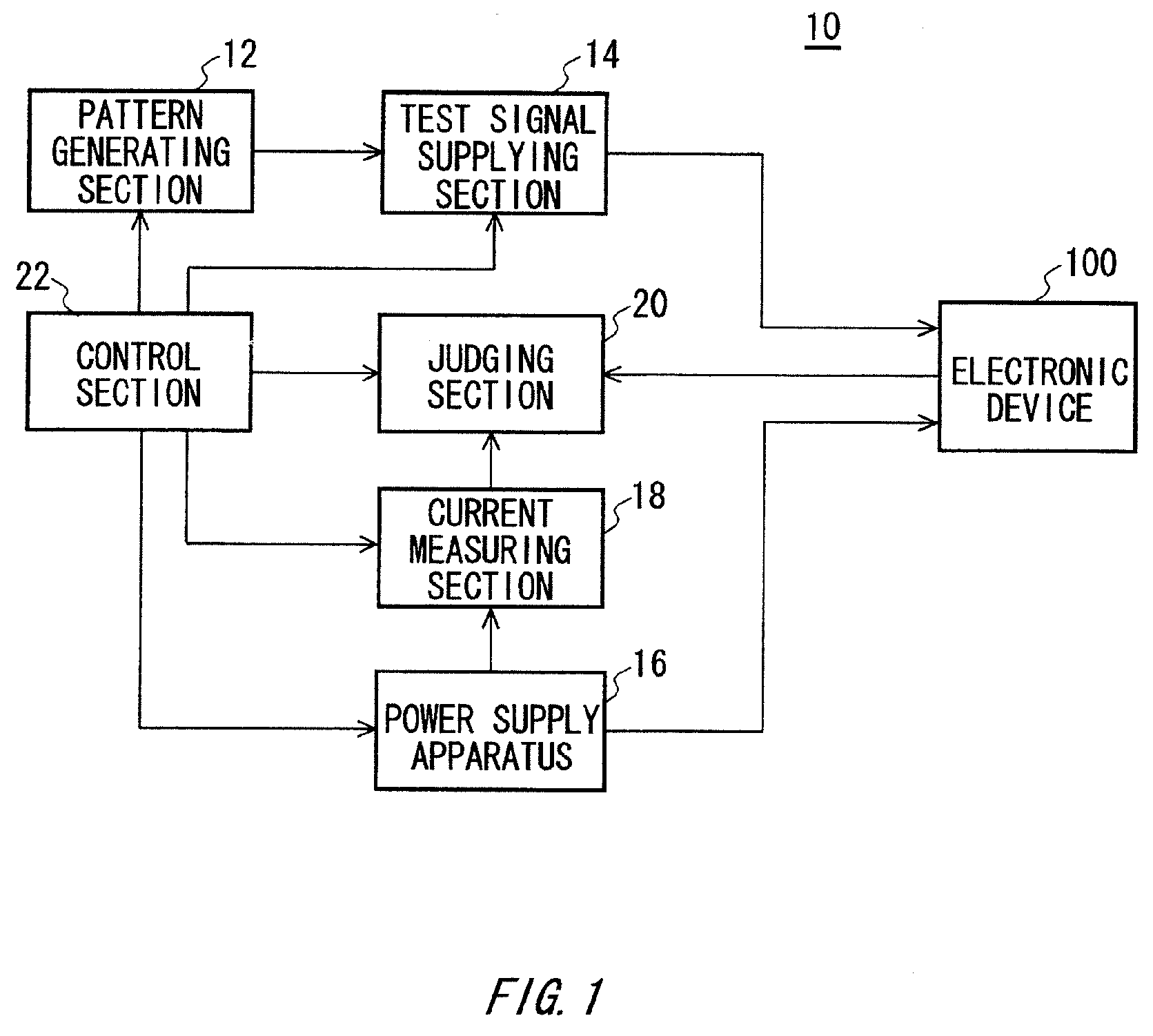
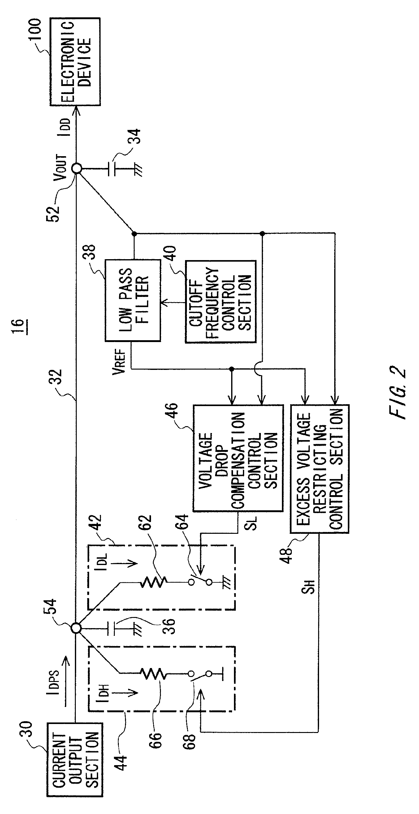
[0022]FIG. 1 shows a configuration of a test apparatus 10 according to an embodiment of the present invention, together with an electronic device 100. The test apparatus 10 tests the electronic device 100, which is a device under test. The test apparatus 10 includes a pattern generating section 12, a test signal supplying section 14, a power supply apparatus 16, a power supply measuring section 18, a judging section 20, and a control section 22.

[0023]The pattern generating section 12 generates a test pattern indicating the pattern of a test signal to be supplied to the electronic device 100. The test signal supplying section 14 supplies the electronic device 100 with the test signal correspondi...


PUM


Abstract

Provided is a power supply apparatus including a low pass filter that receives an output voltage of a current output section and allows a low frequency component with a frequency lower than a preset cutoff frequency to pass through; an excess voltage restricting load section that consumes an excess voltage restricting current, which is at least a portion of the output current from the current output section, when a load is turned on; and an excess voltage restricting control section that keeps the excess voltage restricting load section turned off when the output voltage of the current output section is less than an upper reference voltage, which is obtained by adding together a voltage output by the low pass filter and a preset upper offset voltage.

Description

CROSS REFERENCE TO RELATED APPLICATION[0001]This is a continuation application of PCT / JP2007 / 059323 filed on May 1, 2007 which claims priority from a Japanese Patent Application No. 2006-154076 filed on Jun. 1, 2006, the contents of which are incorporated herein by reference.BACKGROUND[0002]1. Technical Field[0003]The present invention relates to a power supply apparatus, a test apparatus, and a stabilizing apparatus. In particular, the present invention relates to a power supply apparatus, a test apparatus, and a stabilizing apparatus that supply an electronic device with a stabilized power supply voltage. The present patent application claims priority based on a Japanese Patent Application No. 2006-154076 filed on Jun. 1, 2006, the contents of which are incorporated herein by reference.[0004]2. Related Art[0005]A test apparatus that tests an electronic device desirably supplies the electronic device with a power supply voltage having as little fluctuation as possible, even if the ...

Claims


Application Information

Patent Timeline
Patent Type & Authority Patents(United States)
IPC IPC(8): G01R31/28
CPCG01R31/31721G01R31/3004G01R31/31917G01R31/28G05F1/10
Inventor HASHIMOTO, YOSHIHIRO
Owner ADVANTEST CORP
Why Eureka
Try Eureka