
Electronic machine, connected machine identifying method for electronic machine and control system

Inactive Publication Date: 2010-09-28
SONY CORP
View PDF19 Cites 3 Cited by
  • Summary
  • Abstract
  • Description
  • Claims
  • Application Information

AI Technical Summary

Benefits of technology

The patent text describes an improved electronic machine and connected machine identifying method and control system. The machine has a resistance, a connector to connect to different machines, and a detecting section that can identify one state from multiple states based on the resistance value of the machine and the resistance value of the different machine. This allows the machine to accurately identify the connected machine and control multiple parameters based on the detected state. The technical effect of this invention is to provide a more efficient and accurate way to identify and connect different machines to an electronic machine.

Problems solved by technology

However, the method disclosed in Patent Document 1 has a problem that the connection state of only one machine can be identified in an electronic machine.
Today, many machines connectable to an electronic machine such as a portable music player exist, and many machines such as an earphone among the machines may not have an electronic circuit.

Method used


Image

  • Electronic machine, connected machine identifying method for electronic machine and control system
  • Electronic machine, connected machine identifying method for electronic machine and control system
  • Electronic machine, connected machine identifying method for electronic machine and control system

Examples


Embodiment Construction

[0035]With reference to the attached drawings, preferred embodiments of the invention will be described in detail below. In the specification and drawings, identical reference numerals are given to components substantially having identical functional constructions, and repetitive explanation thereon will be omitted herein.

[0036]First of all, the form of a connector of an electronic machine according to an embodiment of the invention will be described. The electronic machine according to the embodiment of the invention is configured to be connectable with a different machine through a connector, such as a portable music player.

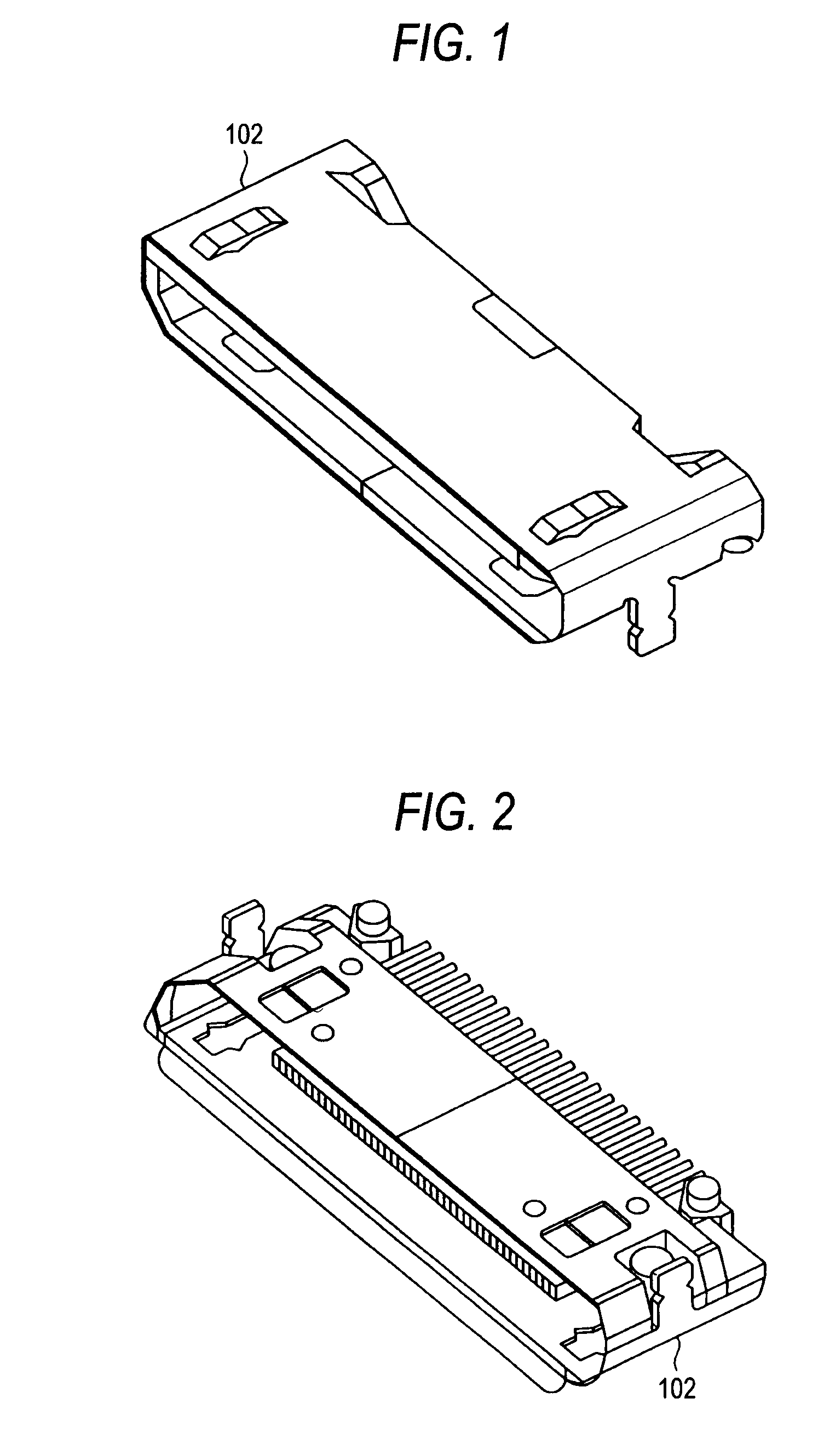
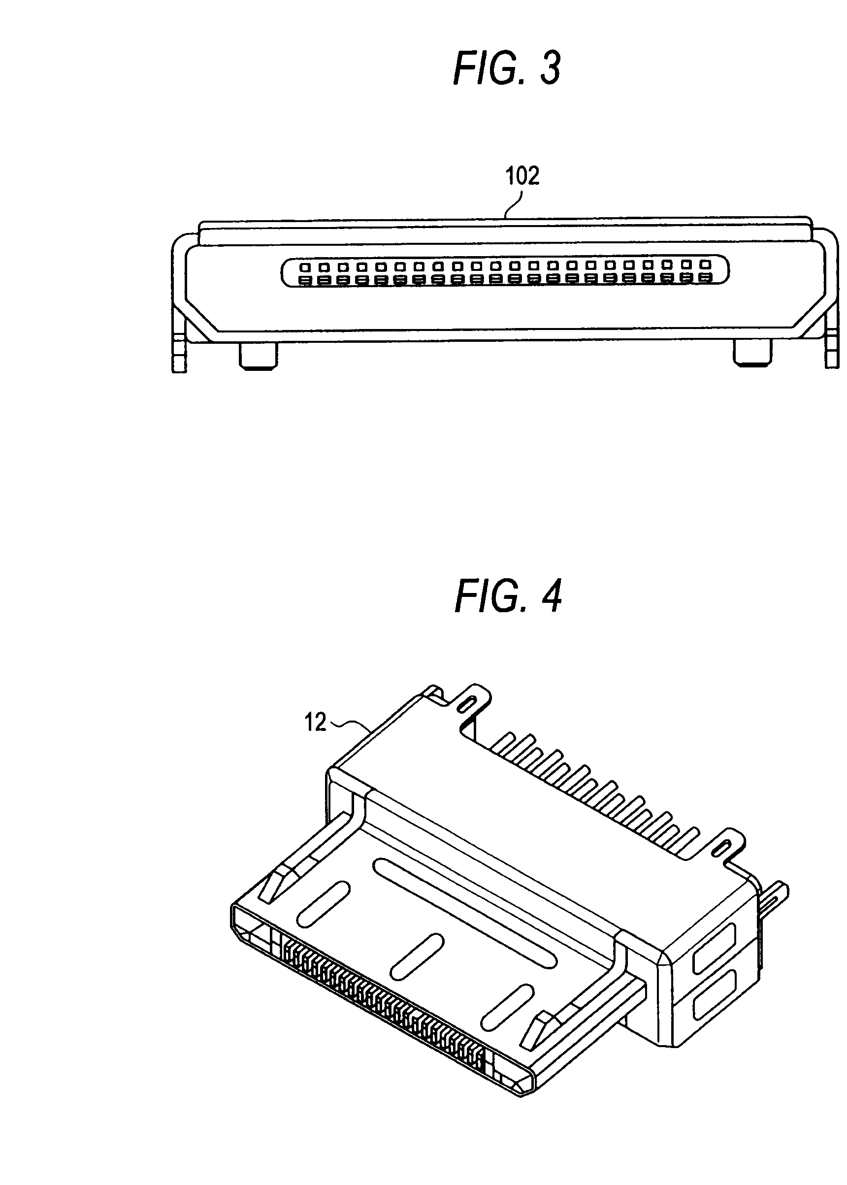
[0037]FIGS. 1 to 3 are explanatory diagrams for describing the form of the connector of the electronic machine according to the embodiment of the invention. With reference to FIGS. 1 to 3, the form of the connector of the electronic machine according to an embodiment of the invention will be described below.

[0038]FIG. 1 is a front perspective view illustrating ...


PUM


Abstract

An electronic machine connectable to a different apparatus is disclosed. The electronic machine includes a resistance, a connector to be connected to the different apparatus, and a detecting section that detects one state from multiple states based on the resistance value of the resistance and the resistance value of a resistance included in the different apparatus connected to the connector and controls multiple parameters based on the detected one state.

Description

CROSS REFERENCES TO RELATED APPLICATIONS[0001]The present invention contains subject matter related to Japanese Patent Applications JP 2006-278053 filed in the Japanese Patent Office on Oct. 11, 2006, the entire contents of which being incorporated herein by reference.BACKGROUND OF THE INVENTION[0002]1. Field of the Invention[0003]The present invention relates to an electronic machine, a connected machine identifying method and a control system.[0004]2. Description of the Related Art[0005]Some electronic machines such as a portable music player may be configured to accept the connection of an external machine such as a headphone, a speaker and a remote controller (these different machines may be called “accessory” hereinafter). Connecting a different machine, that is, an accessory such as an earphone for enjoying music, a personal computer for transferring data and an AC adapter that drives an electronic machine and / or charges a battery thereof to an electronic machine can improve t...

Claims


Application Information

Patent Timeline
Patent Type & Authority Patents(United States)
IPC IPC(8): G01R27/08
CPCG06F13/4081
Inventor IRIE, KENJITAMAYAMA, KENYAMAMOTO, HIROTAKA
Owner SONY CORP
Learn More