Method for determining the risk of rupture of a blood vessel

a risk of rupture and blood vessel technology, applied in the field of medical equipment, can solve the problems of difficult to identify with the naked eye, small anatomy of interest to the physician, and certain significant limitations, and physicians can sometimes have difficulty correlating what they see on one image with what they see on the other imag

Active Publication Date: 2010-09-28
ASTUTE IMAGING LLC
View PDF20 Cites 92 Cited by
  • Summary
  • Abstract
  • Description
  • Claims
  • Application Information

AI Technical Summary

Benefits of technology

[0017]Accordingly, one object of the present invention is to provide an improved anatomical visualization and measurement system for visualizing and measuring anatomical structures.
[0018]Another object of the present invention is to provide an improved anatomical visualization and measurement system wherein a scanned 2-D slice image can be appropriately combined with an image generated from a 3-D database so as to create a single composite image.
[0019]Another object of the present invention is to provide an improved anatomical visualization and measurement system wherein a marker can be placed onto a 2-D slice image displayed on a screen, and this marker will be automatically incorporated, as appropriate, into a 3-D computer model maintained by the system, as well as into any other 2-D slice image data maintained by the system.

Problems solved by technology

Furthermore, in many cases, the anatomical structures of interest to the physician may be quite small and / or difficult to identify with the naked eye.
While the 2-D slice images generated by the aforementioned scanning devices, and / or the 3-D database images generated by the aforementioned associated computer hardware and software, are generally of great benefit to physicians, certain significant limitations still exist.
Unfortunately, physicians can sometimes have difficulty correlating what they see on one image with what they see on another image.
In these situations it can be relatively difficult and / or time-consuming for the physician to accurately measure and record all of the anatomical dimensions needed for proper sizing of the prosthetic device to the patient.
Unfortunately, it can be difficult and / or impossible to make accurate anatomical measurements with existing visualization systems.
Unfortunately, it can be difficult and / or impossible to accurately generate such a view using existing visualization systems.
Unfortunately, it can be difficult and / or impossible to accurately make such a calculation using existing visualization systems.

Method used


Image

  • Method for determining the risk of rupture of a blood vessel
  • Method for determining the risk of rupture of a blood vessel
  • Method for determining the risk of rupture of a blood vessel

Examples


Embodiment Construction

Basic System

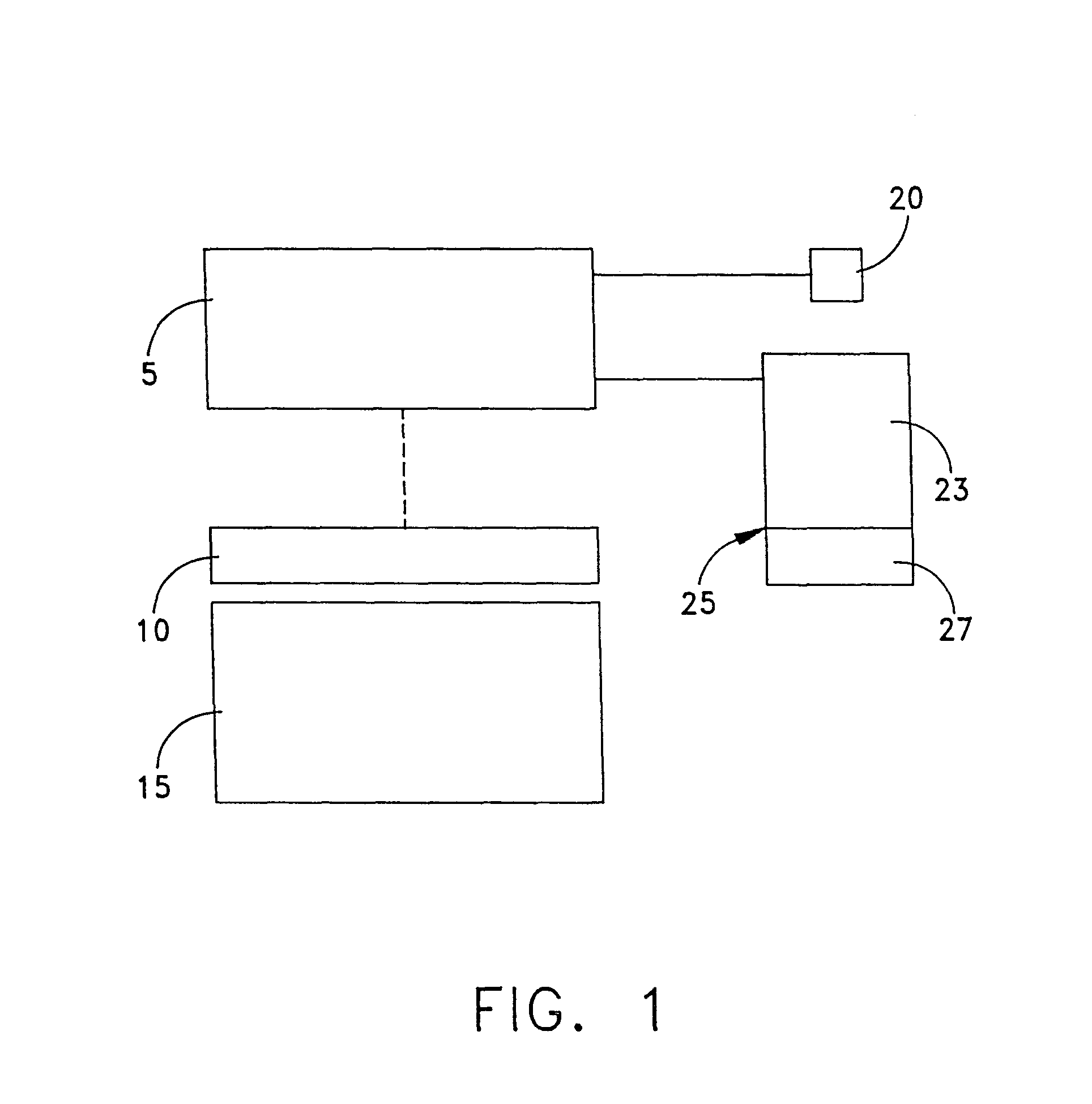
[0097]Looking first at FIG. 1, a scanning device 5 is shown as it scans the interior anatomical structure of a patient 10, as that patient 10 lies on a scanning platform 15.

[0098]Scanning device 5 is of the sort adapted to generate scanning data corresponding to a series of 2-D images, where each 2-D image corresponds to a specific viewing plane or “slice” taken through the patient's body. Furthermore, scanning device 5 is adapted so that the angle and spacing between adjacent image planes or slices can be very well defined, e.g., each image plane or slice may be set parallel to every other image plane or slice, and adjacent image planes or slices may be spaced a pre-determined distance apart. By way of example, the parallel image planes might be set 1 mm apart.

[0099]The scanning data obtained by scanning device 5 can be displayed as a 2-D slice image on a display 20, and / or it can be stored in its 2-D slice image data form in a first section 23 of a data storage device ...


PUM


Abstract

There is provided a method and apparatus for determining the risk of rupture of a blood vessel using a set of 2-D slice images obtained by scanning the blood vessel. The invention includes elements and steps for generating a mesh model of the blood vessel using the set of 2-D slice images, conducting finite element stress analysis on the mesh model to calculate the level of stress on different locations on the mesh model and determining the risk of rupture of the blood vessel based on the calculated levels of stress on different locations on the mesh model.

Description

REFERENCE TO PENDING PRIOR PATENT APPLICATION[0001]This patent application claims benefit of pending prior U.S. Provisional Patent Application Ser. No. 60 / 582,128, filed Jun. 23, 2004 by David Chen et al. for METHOD TO CREATE MESH OBJECTS FOR FINITE ELEMENT ANALYSIS OF BLOOD VESSELS AND POST-ANALYSIS STRESS VISUALIZATION, which patent application is hereby incorporated herein by reference.FIELD OF THE INVENTION[0002]This invention relates to medical apparatus in general, and more particularly to anatomical visualization and measurement systems.BACKGROUND OF THE INVENTION[0003]Many medical procedures must be carried out at an interior anatomical site which is normally hidden from the view of the physician. In these situations, the physician typically uses some sort of scanning device to examine the patient's anatomy at the interior site prior to, and in preparation for, conducting the actual medical procedure. Such scanning devices typically include CT scanners, MRI devices, X-ray ma...

Claims


Application Information

Patent Timeline
Patent Type & Authority Patents(United States)
IPC IPC(8): A61N1/362
CPCA61B5/02007A61B5/055A61B6/032A61B6/466A61B6/504
Inventor CHEN, DAVID T.DWYER, JEFFFILLINGER, MARK F.MARRA, STEVEN P.CHAPMAN, M. WESTON
Owner ASTUTE IMAGING LLC
Why Eureka
Try Eureka