Airway device

a technology of airway and spleen, which is applied in the field of medical devices, can solve the problems of not being practical to have a buccal cavity stabiliser, and achieve the effect of preventing the possibility of regurgitation and good sealing

Active Publication Date: 2010-10-05
INTERSURGICAL UAB
View PDF137 Cites 37 Cited by
  • Summary
  • Abstract
  • Description
  • Claims
  • Application Information

AI Technical Summary

Benefits of technology

[0011]Such an airway device is both efficient in operation and cost-effective to manufacture.
[0024]Preferably said connector extends into said airway tube and at least part way along the length of said airway tube to act as a bite protector to prevent a patient from constricting the airway tube by biting on it.
[0026]Preferably the distal end of the connector abuts in use a shoulder in the airway tube to prevent the connector from passing into the airway tube beyond a certain point. This provides a positive fit for the connector which seats on a shoulder or recess within the tube, and results in lower resistance to airflow through the device.
[0028]Preferably the face of the laryngeal cuff adapted to form an anatomical fit over the laryngeal inlet of a patient incorporates protuberances designed to form a good seal with the valleculae, epiglottis, aryepiglottic folds, pyriform fossae and around the anterior aspect of thyroid & cricoid cartilages. The distal tip of the device positions itself into the recess created by the posterior aspect of the lower larynx below the posterior cartilages, above the opening of the oesophagus, not only to help create an airway seal but also to act as a physical wedge to prevent the possibility of regurgitation.

Problems solved by technology

It has now unexpectedly been discovered that a stabiliser, whilst still desirable, is not essential to achieve a good gas-tight seal between the cuff and the laryngeal inlet of the patient.
In fact there are several applications where it is just not practical to have a buccal cavity stabiliser.

Method used


Image

  • Airway device
  • Airway device
  • Airway device

Examples


Embodiment Construction

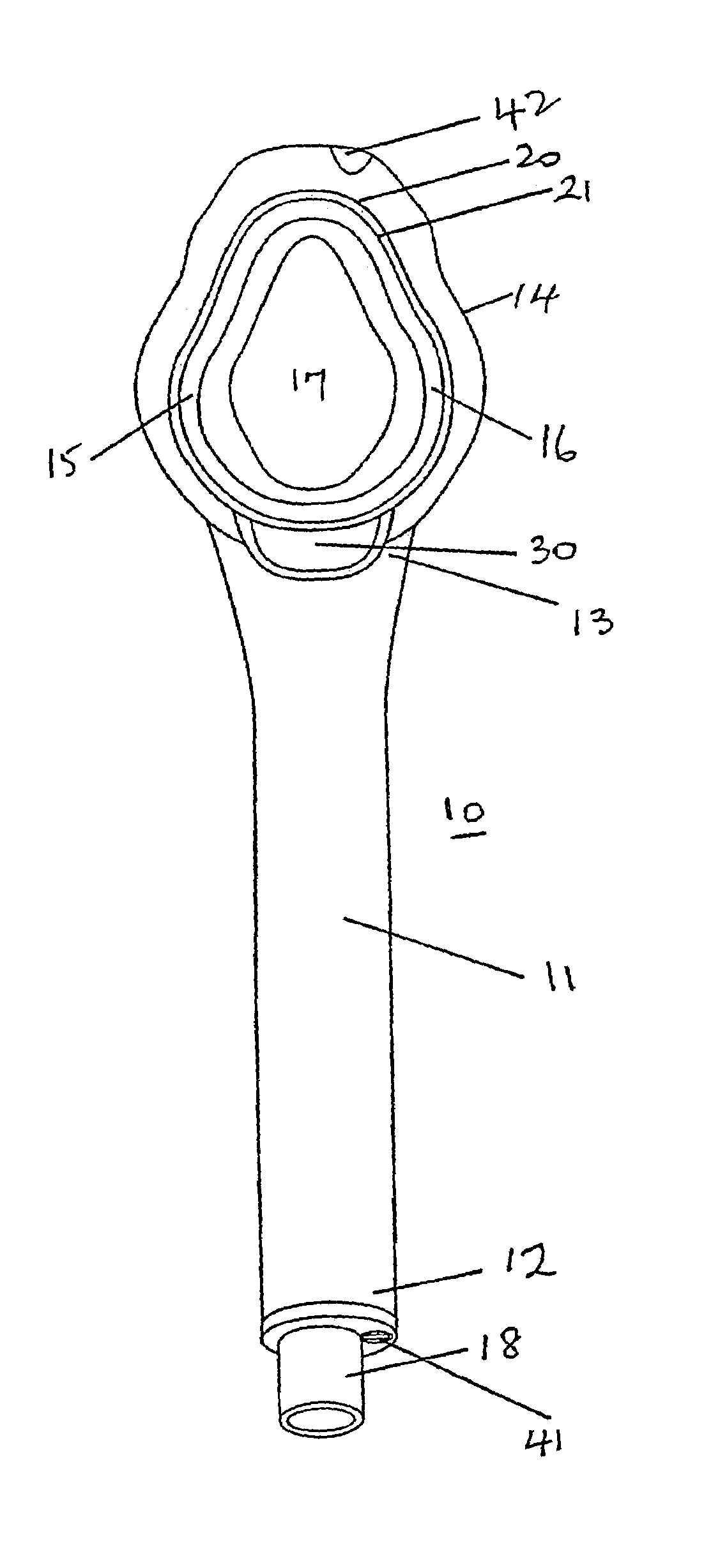
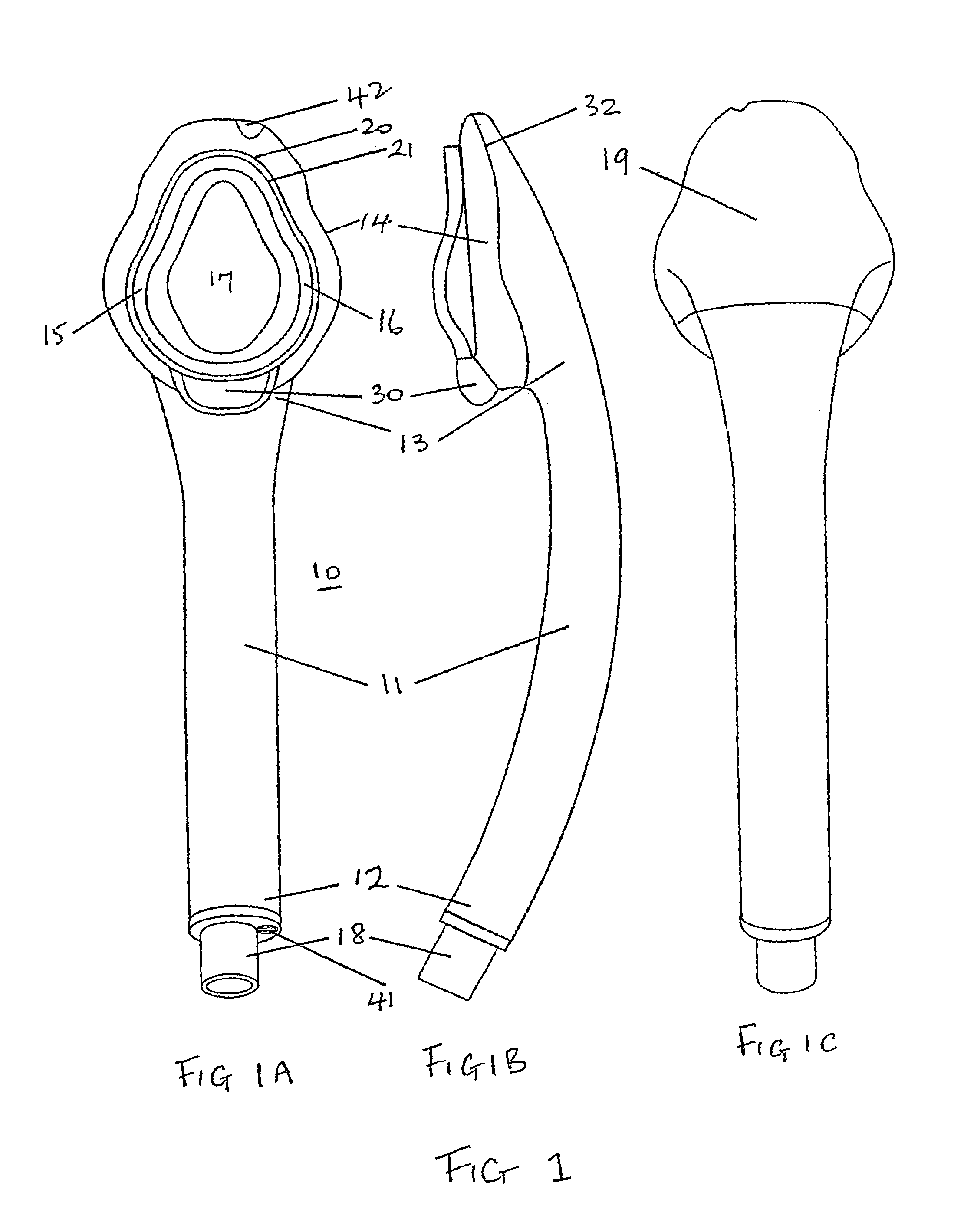
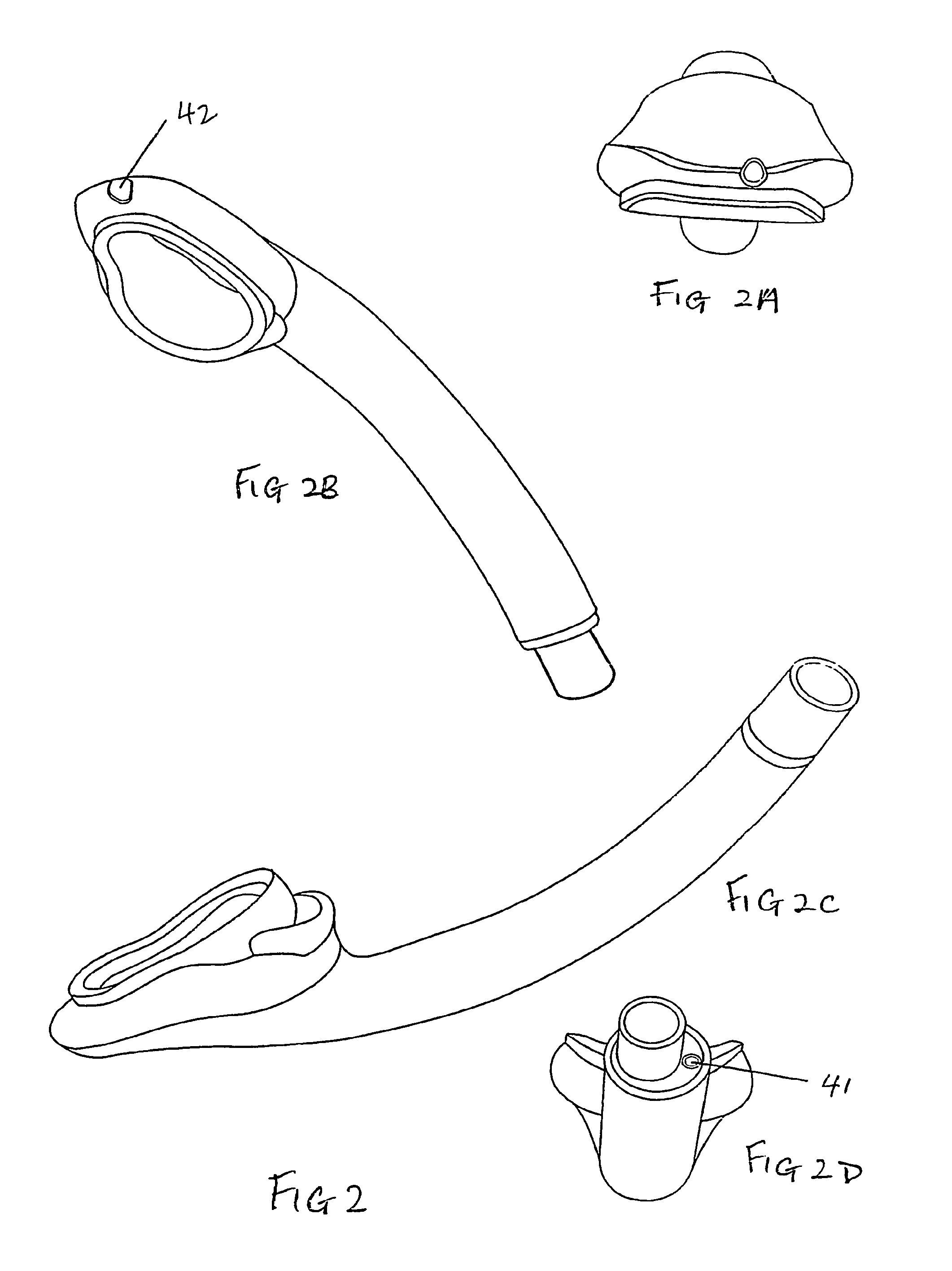
[0080]Embodiments of the present invention are described below by way of example only. These examples represent the best ways of putting the invention into practice that are currently known to the applicant although they are not the only ways in which this could be achieved.

[0081]As used herein, the anatomical terms “anterior” and “posterior,” with respect to the human body, refer to locations nearer to the front of and to the back of the body, respectively, relative to other locations. In the context of this description, the term “proximal” means the end of the device, or portion thereof, closest to the connection to the anaesthetic breathing system. The term “distal” means the end of the device, or portion thereof, furthest from the anaesthetic breathing system or alternatively, the cuff end of the device. The term “lateral” refers to a location to the right or left sides of the body, relative to other locations. “Bilateral” refers to locations both to the left and right of the bo...


PUM

PropertyMeasurementUnit
Shore hardnessaaaaaaaaaa

Abstract

An airway device for human or animal use comprising an airway tube having a distal end and a proximal end, the distal end of which is surrounded by a laryngeal cuff, wherein the cuff is non-inflatable and is pre-formed in a shape such that a face region of the cuff is adapted to fit snugly over the laryngeal inlet of a patient, and wherein the external profile of the tube is substantially uniform between the distal end of the tube where it starts to meet the cuff and the proximal end of the tube, and wherein the face region of the cuff is formed from a material with a Shore hardness on the A scale of between 0 to 30.

Description

FIELD OF THE INVENTION[0001]The present invention relates to medical devices and is particularly applicable, but in no way limited, to laryngeal airway devices and to their methods of manufacture.BACKGROUND TO THE INVENTION[0002]A wide variety of devices are known and are currently used in spontaneously breathing anaesthetized patients, during recovering after anaesthetics, in weaning of a certain group of patients in intensive care, or during resuscitation to provide a clear and hands-free airway. A number of these devices are listed in the applicant's co-pending earlier application GB2,393,399A (Nasir), the text of which is hereby imported by reference and which is intended to form an integral part of this disclosure. GB2,393,399A describes a new type of airway device which has a soft laryngeal cuff adapted to fit anatomically over and form a seal with the laryngeal structure of a patient. An essential feature of certain embodiments of this device is a so-called buccal cavity stab...

Claims


Application Information

Patent Timeline
Patent Type & Authority Patents(United States)
IPC IPC(8): A61M11/00A61M16/04
CPCA61M16/04A61M16/0409A61M16/0415A61M16/0431A61M16/0436A61M16/0443A61M16/0493B29C45/14
Inventor NASIR, MUHAMMED ASLEM
Owner INTERSURGICAL UAB
Why Eureka
Try Eureka