
X-ray CT apparatus

a technology of computed tomography and apparatus, which is applied in the field of x-ray ct (computed tomography) system, can solve the problems of increasing the temperature of the air in the gantry, reducing the airflow present in the surroundings of the x-ray detector,

Inactive Publication Date: 2010-10-05
TOSHIBA MEDICAL SYST CORP
View PDF2 Cites 7 Cited by
  • Summary
  • Abstract
  • Description
  • Claims
  • Application Information

AI Technical Summary

Benefits of technology

This configuration enhances cooling efficiency by reducing non-contributory airflow, preventing temperature increases, and ensuring effective heat dissipation around the X-ray detector, thereby improving the overall performance of the X-ray CT system.

Problems solved by technology

This raises a disadvantage of a decrease in an airflow which is present in the surroundings of the X-ray detector.
The high-temperature air is again taken into the gantry from the air inlet, and hence there is a disadvantage of an increase in the temperature of the air in the gantry.

Method used


Image

  • X-ray CT apparatus
  • X-ray CT apparatus
  • X-ray CT apparatus

Examples


Embodiment Construction

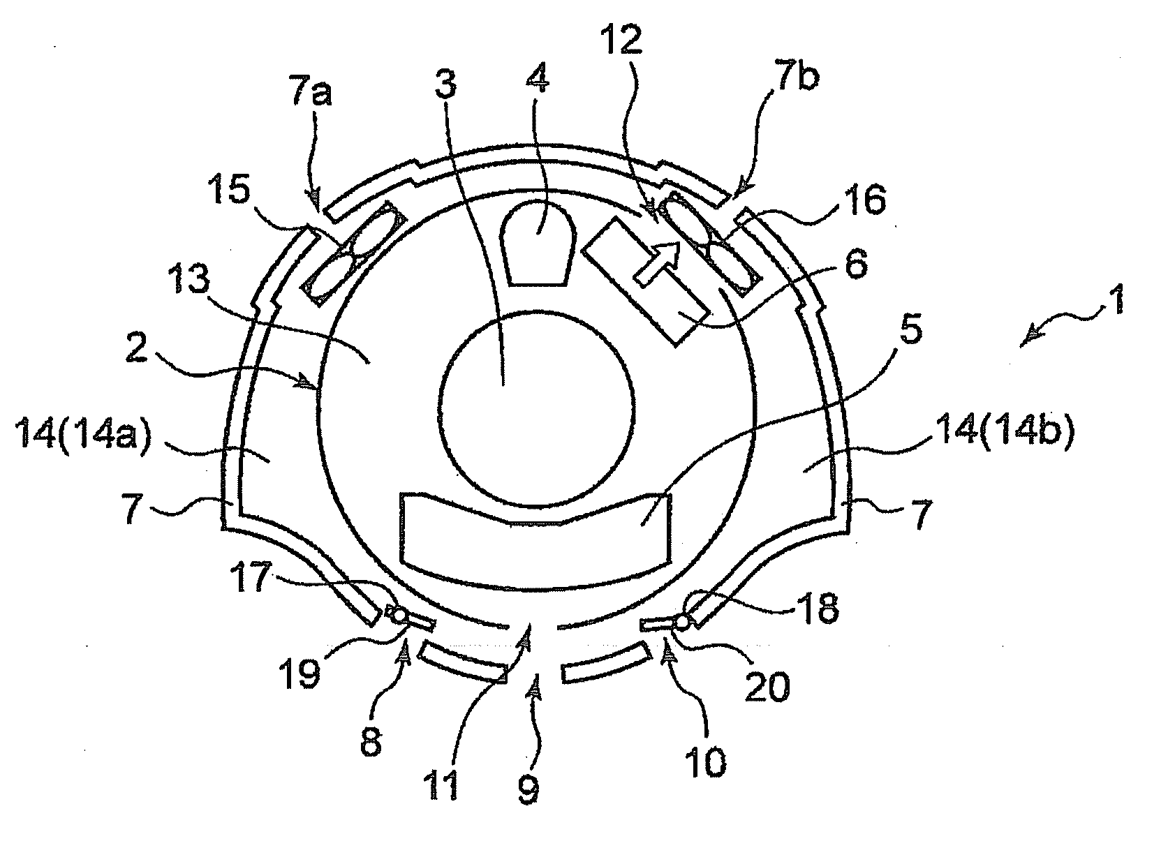
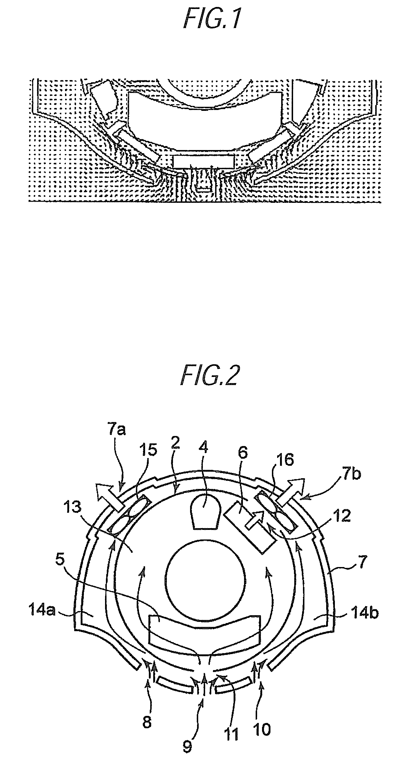
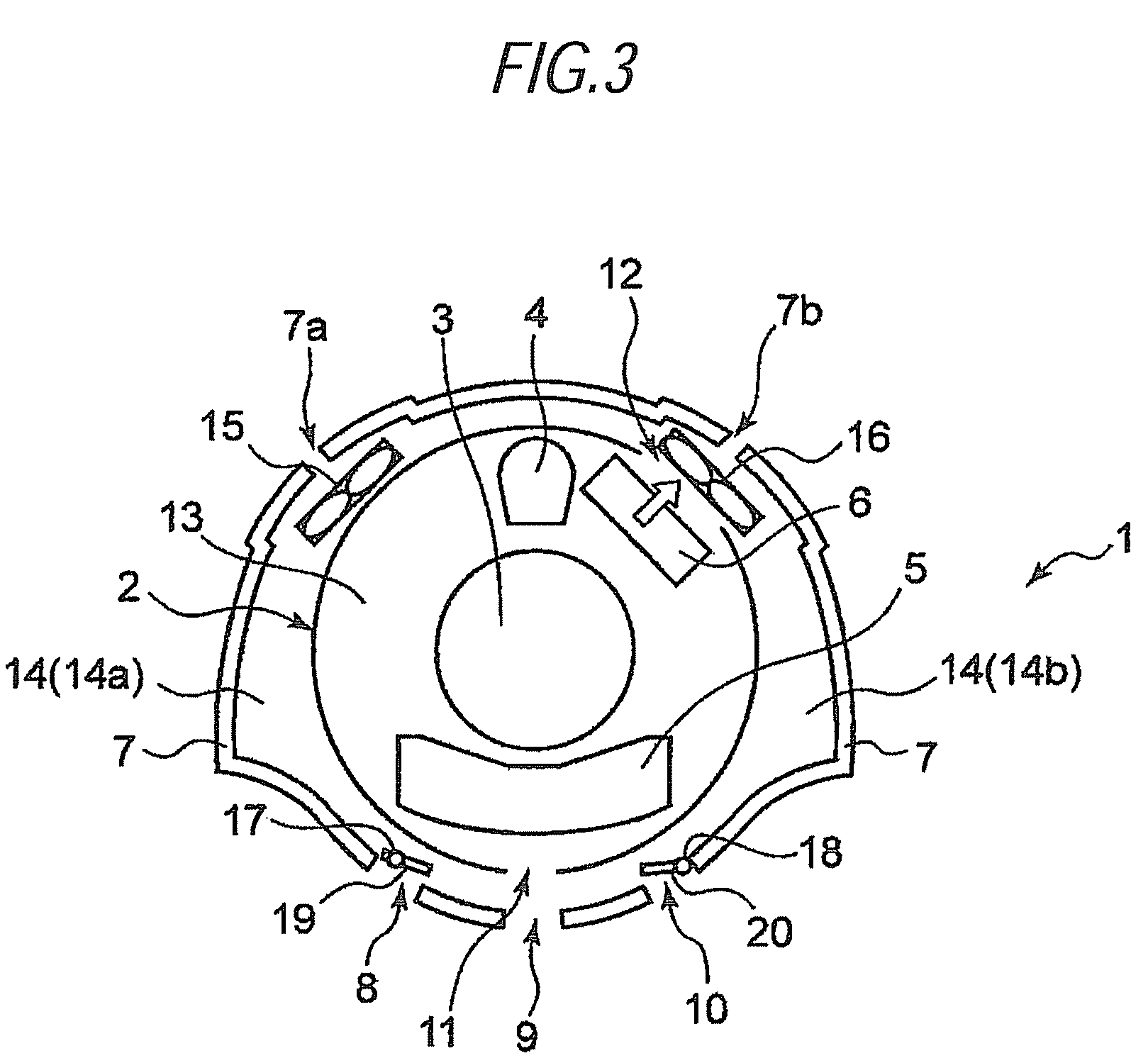
[0021]An X-ray CT apparatus of an embodiment of the present invention will be described hereunder by reference to FIGS. 1 through 9. Throughout the drawings, like elements are assigned like reference numerals, and their repeated explanations are omitted.

[0022]Prior to description of an embodiment, a result of analysis of a hot fluid performed by the present inventors by means of a related-art X-ray CT apparatus will be described by reference to FIGS. 1 and 2. FIG. 1 is a view showing a result of analysis of a hot fluid in a CT gantry (a velocity vector diagram) not having baffle plates achieved when a rotator is stationary. The drawings show a result of simulation obtained by use of fluid analysis software in relation to the analysis of a hot fluid in the CT gantry. As can be seen from the velocity vector, when the rotator is stationary, air flows from the air intake-and-exhaust opened in a lower portion of a gantry cover, and air flow upwardly moving from a lower position within th...


PUM


Abstract

According to the invention, an X-ray CT apparatus includes: an annular rotator including: an X-ray tube; an X-ray detector disposed oppositely to the X-ray tube; a radiator disposed in the vicinity of the X-ray tube and dissipating heat from the X-ray tube; an air outlet provided in the vicinity of the radiator; and an air inlet provided at a position oppositely to the air outlet, a gantry cover covering peripheral of the annular rotator and having an upper air vent and a plurality of lower air vents; a plurality of fans discharging to the outside air exist in a gap between the gantry cover and the annular rotator from the air outlet; and a baffle plate provided in the gap in the vicinity of the lower air vents and controlling an air flow passing through internal space of the annular rotator and an airflow passing through the gap.

Description

CROSS-REFERENCE TO RELATED APPLICATIONS[0001]This application is based upon and claims the benefit of priority from Japanese Patent Application No. 2008-066367, filed Mar. 14, 2008, the entire contents of which are incorporated herein by reference.BACKGROUND[0002]1. Field[0003]The present invention relates to an X-ray CT (Computed Tomography) system.[0004]2. Description of the Related Art[0005]An X-ray CT apparatus captures an X-ray tomography of a subject by means of X-ray radiation. In order to effectively dissipate heat originating from an X-ray tube, the X-ray CT apparatus has a structure that efficiently dissipates internally-generated heat to the outside, thereby efficiently cooling the surroundings of an X-ray detector.[0006]A technique intended for efficiently dissipating the heat generated in the CT apparatus to the outside is proposed in JP-A-2001-238876; specifically, an air inlet is opened in a left bottom surface of a gantry when the gantry is viewed from the front; an ...

Claims


Application Information

Patent Timeline
Patent Type & Authority Patents(United States)
IPC IPC(8): H01J35/10
CPCA61B6/035A61B6/4488H01J2235/1216H01J2235/1262
Inventor JIMBO, TOMOHIKOIWASAKI, HIDEOTAKAMATSU, TOMONAO
Owner TOSHIBA MEDICAL SYST CORP
Learn More