Rotor for laboratory centrifuges with hold-down element for centrifugation containers

Active Publication Date: 2010-10-05
THERMO ELECTRONICS LED GMBH
View PDF31 Cites 2 Cited by
  • Summary
  • Abstract
  • Description
  • Claims
  • Application Information

AI Technical Summary

Benefits of technology

[0035]In one preferred embodiment, multiple hold-down elements are provided on one adapter, and cooperate to hold the adapter in the rotor. In this regard, it is advantageous that in this manner large forces may be absorbed, thereby ensuring a secure bearing of the adapter in the rotor.
[0036]The hold-down element is advantageously designed as a catch element which engages with a counterpart located in the rotor. The locking connection is designed to be detachable, and thus ensures easy insertion and removal of the adapter into and out of the rotor.
[0037]Alternatively, it is advantageous to design the hold-down element as a spring element. The spring element is situated between the adapter and the r

Problems solved by technology

During the loading or unloading process or also during operation, the centrifugation containers may be accidentally moved from the operating position.
In particular when sample vessels are removed, the adapter in which the sample vessel is situated may inadvertentl

Method used


Image

  • Rotor for laboratory centrifuges with hold-down element for centrifugation containers
  • Rotor for laboratory centrifuges with hold-down element for centrifugation containers
  • Rotor for laboratory centrifuges with hold-down element for centrifugation containers

Examples


Embodiment Construction

[0047]In the various embodiments of the present invention illustrated in the figures, identical components are provided with the same reference numbers.

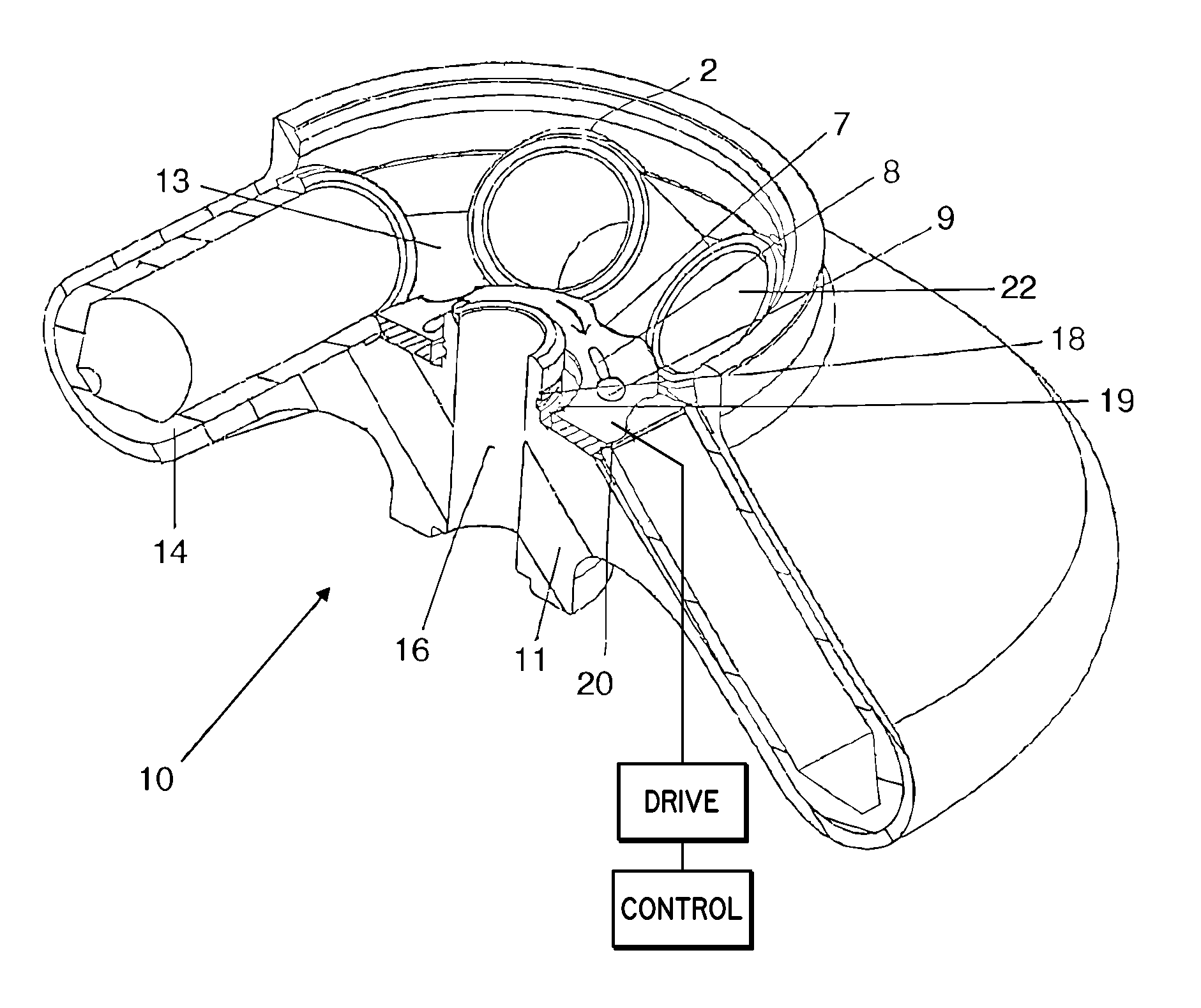
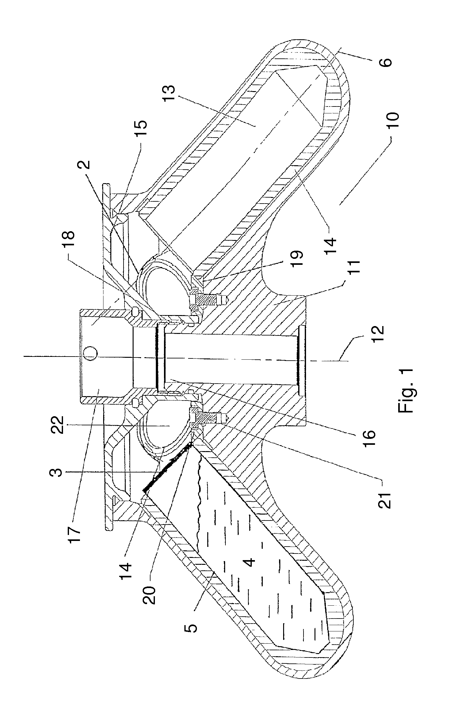
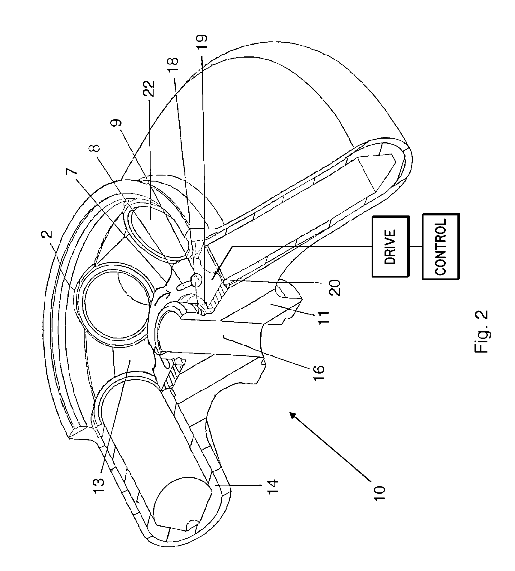
[0048]FIG. 1 shows a cross section of a rotor 10 for laboratory centrifuges. The rotor 10 has the shape of a truncated cone, having an upwardly tapering rotor body 11. An annular trough 13, situated concentrically around the rotor axis 12, is also provided in the outer region of the rotor 10. Inside the annular trough 13, adapters 14 are situated at regular intervals in the circumferential direction which are designed for accommodating sample vessels 5. The sample vessels 5 have a lid 3 at their upper ends, and are filed with sample liquid 4.

[0049]The adapters 14 are designed essentially as hollow cylinders which are closed at the bottom and open at their upper end face. Arch-shaped recesses 2 are provided in the outer wall of the annular trough which are designed to respectively accommodate one adapter 14 with a positive fit and to ...


PUM


Abstract

The invention relates to a rotor for laboratory centrifuges which is designed for accommodating at least one centrifugation container, and an adapter for accommodating a sample vessel and for use in a laboratory centrifuge rotor. The rotor has at least one hold-down element by which the at least one centrifugation container is held in the rotor and protected from axial displacement. In addition, a contact pressure may be produced on the at least one centrifugation container on the rotor.

Description

CROSS REFERENCE TO RELATED APPLICATIONS[0001]This application claims priority to German Patent Application Serial No. 102004062232.9, filed Dec. 23, 2004 entitled, ROTOR FOR LABORATORY CENTRIFUGES, the disclosure of which is incorporated by reference in its entirety.FIELD OF THE INVENTION[0002]The invention relates to a rotor for laboratory centrifuges which is designed for accommodating at least one centrifugation container, and an adapter for accommodating a sample vessel and for use in a laboratory centrifuge rotor.BACKGROUND OF THE INVENTION[0003]In the present context, a centrifugation container on the one hand may be a sample vessel in which the samples to be centrifuged are placed. On the other hand, a centrifugation container may also be an adapter which may be inserted into a rotor and in which, in turn, a sample vessel may be placed.[0004]The invention preferably relates to a fixed-angle rotor having a circumferential annular trough, situated concentrically about the rotor...

Claims


Application Information

Patent Timeline
IPC IPC(8): B04B5/02
CPCB04B5/0414B04B7/08B04B2007/025B04B5/0407
Inventor EIGEMEIER, FRANK
Owner THERMO ELECTRONICS LED GMBH
Why Eureka
Try Eureka