Displaying apparatus using data line driving circuit and data line driving method

a technology of data line driving circuit and display apparatus, which is applied in the field of display apparatus, can solve the problems of lack of write current to the pixel, increase in electric power consumption, and uneven display of display apparatus, and achieve the effect of improving display unevenness and reducing the number of data lines driving the display apparatus

Active Publication Date: 2010-10-05
RENESAS ELECTRONICS CORP
View PDF19 Cites 13 Cited by
  • Summary
  • Abstract
  • Description
  • Claims
  • Application Information

AI Technical Summary

Benefits of technology

[0020]As mentioned above, according to the present invention, the display unevenness of the display apparatus can be improved.
[0021]Also, the chip area of the driver IC for driving the data line of the display apparatus can be reduced.

Problems solved by technology

Thus, in the driver IC in which the time divisional switch is used to perform the time division drive on the amorphous TFT, the coupling capacitance value between the wirings influences a signal on the adjacent data line to indicate an undesirable signal value and brings about a display unevenness.
However, the increase in the parasitic capacitance Cd is not preferred because not only the electric power consumption is increased, but also the lack of the write current to the pixel is caused.
Thus, since the wiring length of the display signal line becomes long, the parasitic capacitance is made larger, which increases the electric power consumption.

Method used


Image

  • Displaying apparatus using data line driving circuit and data line driving method
  • Displaying apparatus using data line driving circuit and data line driving method
  • Displaying apparatus using data line driving circuit and data line driving method

Examples


first embodiment

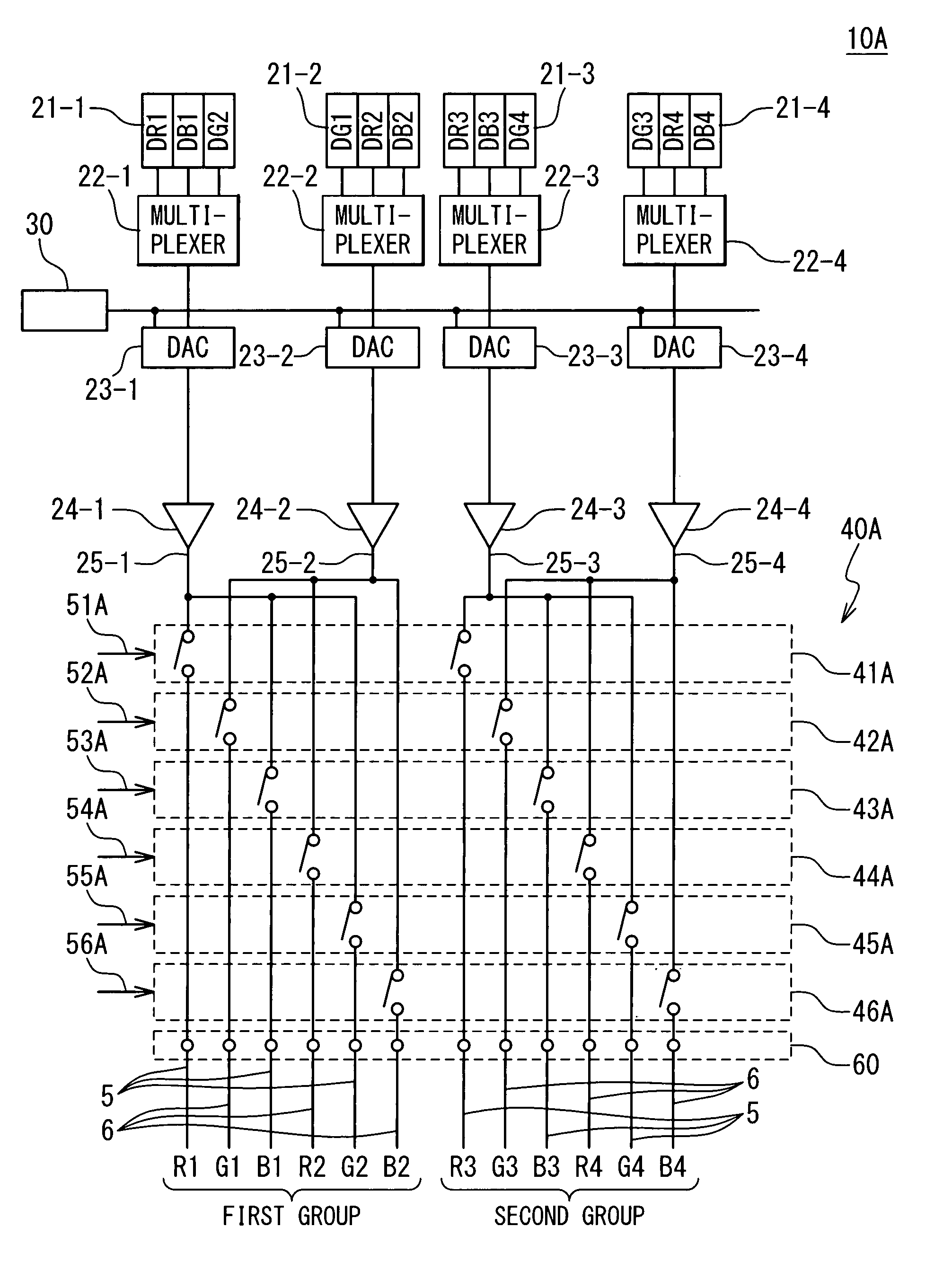
[0042]The display apparatus with the data line driving circuit according to the first embodiment of the present invention will be described below with reference to FIGS. 3 to 7. The display apparatus 100 in the first embodiment includes a data line driving circuit 10A as the data line driving circuit 10 in FIG. 3.

[0043]FIG. 4 is a circuit diagram showing a configuration of the data line driving circuit 10A in the first embodiment. With reference to FIG. 4, the configuration of the data line driving circuit 10A in the first embodiment will be described in detail. The data line driving circuit 10A is a circuit for sending display signals through the plurality of data lines 5 and 6 to the pixels 7, and contains at least data latches 21 (21-1 to 21-4), multiplexers 22 (22-1 to 22-4), D / A converters (DAC: Digital Analog Converter) 23 (23-1 to 23-4), buffers 24 (24-1 to 24-4), a gray scale voltage generating circuit 30 and a time divisional switch group 40A. Moreover, although not shown, ...

second embodiment

[0068]The display apparatus with the data line driving circuit 10 according to the second embodiment of the present invention will be described below with reference to FIG. 3 and FIGS. 8 to 11. The display apparatus 100 in the second embodiment includes a data line driving circuit 10B for performing a dot inversion drive on the pixel 7, as the data line driving circuit 10 in FIG. 3. The dot inversion drive is a driving method in which the polarities of the pixels 7 adjacent in the up, down, left and right directions are different. In the dot inversion drive, the voltage of the common electrode is typically fixed. Then, the polarity is inverted by the data line driving circuit 10B. In this embodiment, a case that the number of the data lines in one group is 3 will be described as one example. Here, the number of the data lines in one group is odd. Thus, the number of the data lines driven in one buffer 24 is 5 or 4. It should be noted that the number of the data lines and the number ...

third embodiment

[0100]The data line driving circuit 10 according to the third embodiment of the present invention will be described below with reference to FIG. 3 and FIG. 12, FIGS. 13A to 13G, and FIG. 14. The display apparatus 100 in the third embodiment includes a data line driving circuit 10C for performing a dot inversion drive on the pixel 7, as the data line driving circuit 10 in FIG. 3. The dot inversion drive is a drive method so that the polarities of the pixels 7 adjacent to each other in the up, down, left and right directions are different. In the dot inversion drive, the voltage of the common electrode is typically fixed. Then, the polarity is inverted by the data line driving circuit 10C. In this embodiment, a case that the number of the data lines in one group is 6 will be described as one example.

[0101]FIG. 12 is a circuit diagram showing the configuration of the data line driving circuit 10C in the third embodiment. The configuration of the data line driving circuit 10C in the thi...


PUM


Abstract

A data line driving circuit includes a first buffer circuit configured to drive a data line, and a second buffer circuit configured to drive a data line. N first data lines (n is a natural number larger than 1), and m second data lines (m is a natural number larger than 1) are alternately arranged in units of data lines as a group. The data line driving circuit further includes a first switch circuit configured to select one of the n first data lines in a first ON period and to connect the selected first data line with the first buffer circuit, and a second switch circuit configured to select one of the m second data lines adjacent to the selected first data line in a second ON period and to connect the selected second data line with the second buffer circuit.

Description

BACKGROUND OF THE INVENTION[0001]1. Field of the Invention[0002]The present invention relates to a display apparatus, and more particularly relates to a display apparatus with a data line driving circuit, and a data line driving method.[0003]2. Description of Related Art[0004]A time division drive, in which a plurality of data lines are sequentially selected and consequently display signals are written into pixels, is one of techniques that are widely used for a display apparatus. A merit of the time division drive is to make it possible to reduce the number of the buffers provided in a driver IC. The display apparatus that employs the time division drive can drive the pixels by using the buffers whose number is smaller than the number of the data lines on a panel. This is effective for decreasing the electric power consumption and chip area of the driver IC.[0005]The display apparatus of an active matrix type uses a TFT (Thin Film Transistor) as a time divisional switching element ...

Claims


Application Information

Patent Timeline
Patent Type & Authority Patents(United States)
IPC IPC(8): G06F3/038
CPCG09G3/3688G09G3/2003G09G3/2011G09G3/3614G09G3/3696G09G2310/0218G09G2310/027G09G2310/0297G09G2310/065G09G2320/0209G09G2330/028
Inventor HASHIMOTO, YOSHIHARUSHU, TAKAYUKI
Owner RENESAS ELECTRONICS CORP
Why Eureka
Try Eureka