

Network device architecture for centralized packet processing
a network device and packet processing technology, applied in the field of information networks, can solve problems such as difficulty in managing what can become a very large number of access layer devices, and difficulty in managing such a large number of devices
- Summary
- Abstract
- Description
- Claims
- Application Information
AI Technical Summary
Benefits of technology
Problems solved by technology
Method used
Image

Examples
Embodiment Construction
[0042]The following is intended to provide a detailed description of an example of the invention and should not be taken to be limiting of the invention itself. Rather, any number of variations may fall within the scope of the invention which is defined in the claims following the description.
Introduction
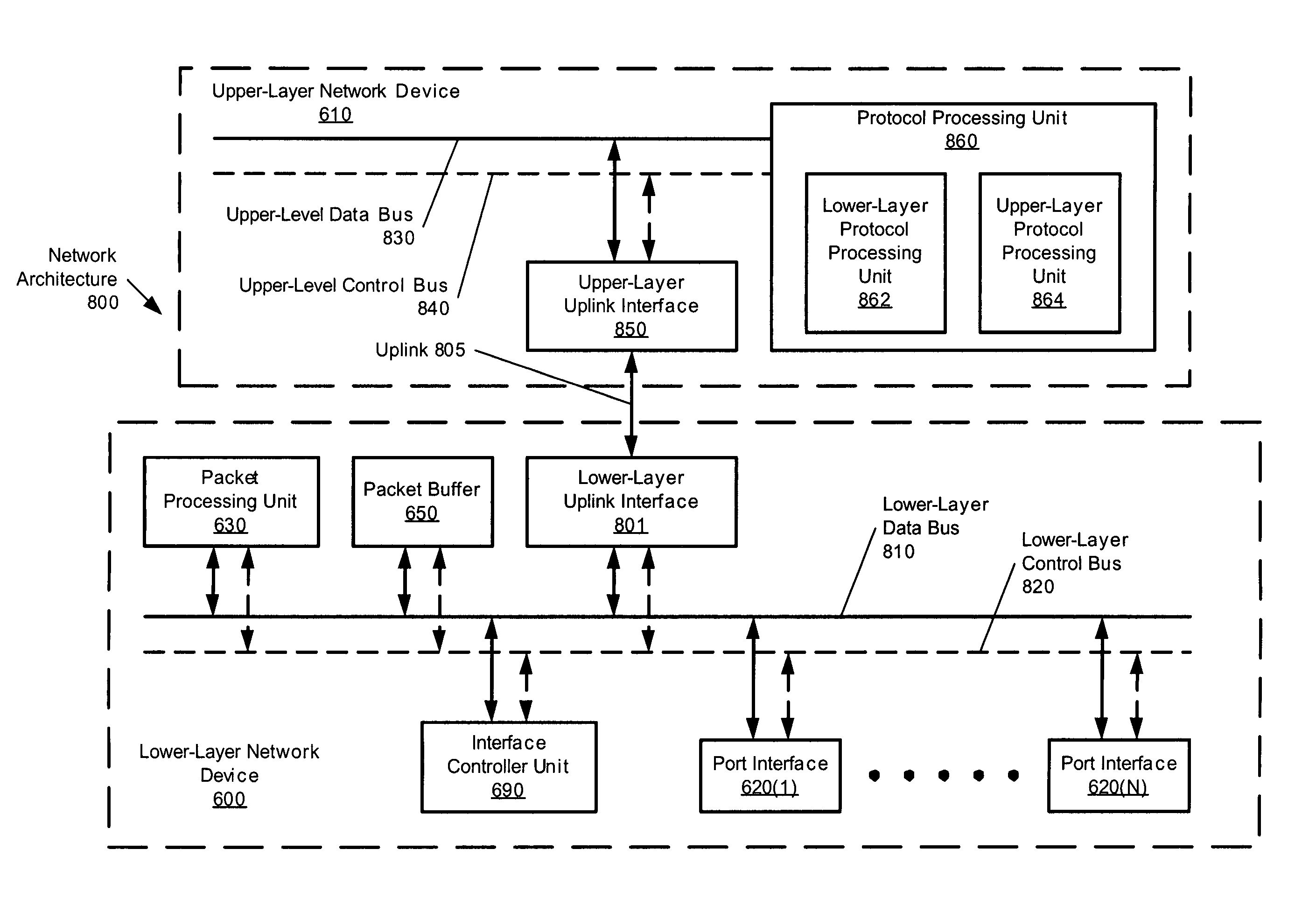
[0043]The present invention provides a method and apparatus that addresses the limitations outlined earlier by providing a network device architecture that supports a more centralized approach to packet processing, as well as a method of operating such a network device. In an architecture of the present invention, a lower-layer network device relies on the upper-layer network device to which the lower-layer network device is coupled, to perform packet processing traditionally performed by the lower-layer network device (i.e., lower-layer protocol processing), in addition to the packet processing traditionally performed by the upper-layer network device (i.e., upper-layer protocol pr...
PUM
 Abstract
Description
Claims
Application Information