Camera arrangement behind an inclined pane

a technology of panes and cameras, applied in the field of camera arrangements, can solve the problems of inability to align the camera and the camera cannot detect, and achieve the effect of reducing the blind angl

Active Publication Date: 2010-10-12
LEOPOLD KOSTAL GMBH & CO KG
View PDF28 Cites 45 Cited by
  • Summary
  • Abstract
  • Description
  • Claims
  • Application Information

AI Technical Summary

Benefits of technology

[0012]A light ray incident on a pane having parallel faces from a non-perpendicular direction continues to pass in the direction of incidence, having undergone a slight parallel displacement after passing through the pane, because the refraction of the light ray toward the perpendicular at the point of entry into the pane is cancelled by refraction away from the perpendicular as the light ray exits the pane. Thus, the angular region detected by a camera through the pane is insignificantly altered. For various reasons such as minimizing space requirements, prevention of reflections on the inner sides of the panes, protection against vandalism and environmental effects, etc., it is necessary to mount the camera near the pane and to screen the camera and the region of light passage between camera and the pane by a housing. These requirements can generally be fulfilled in cases where the camera points almost perpendicularly through the pane. However, when a part of the outside space near the pane surface is to be detected, the camera must be pointed at a shallow angle to the plane. This is often disadvantageous due to the space requirement of the camera and the resulting large screening.
[0013]In embodiments of the present invention, a light-guiding element is between the camera and the pane. The light-guiding element include a prism or a combination of prisms. The light-guiding element cancels the refraction effect behind the pane such that light rays emanating from a comparatively large angular region in front of the pane are transmitted into a comparatively small angular region behind the pane and can thus be detected by the camera.

Problems solved by technology

Because of space requirements of the camera, it is generally not possible to align the camera relative to the pane such that the detection region extends along the surface of the pane.
Consequently, the camera has a blind region in which the camera cannot detect light rays which are incident to the pane at an angle nearly parallel to the surface of the pane (i.e., light rays which have a glancing angle of incidence).

Method used


Image

  • Camera arrangement behind an inclined pane
  • Camera arrangement behind an inclined pane

Examples


Embodiment Construction

)

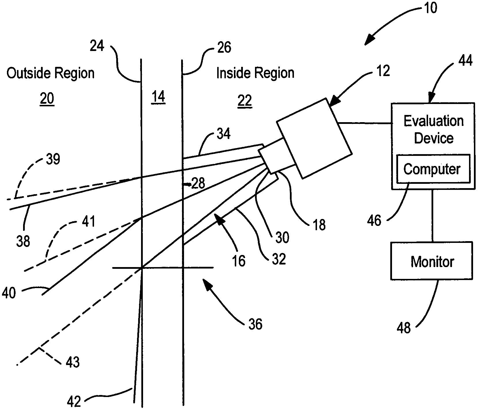
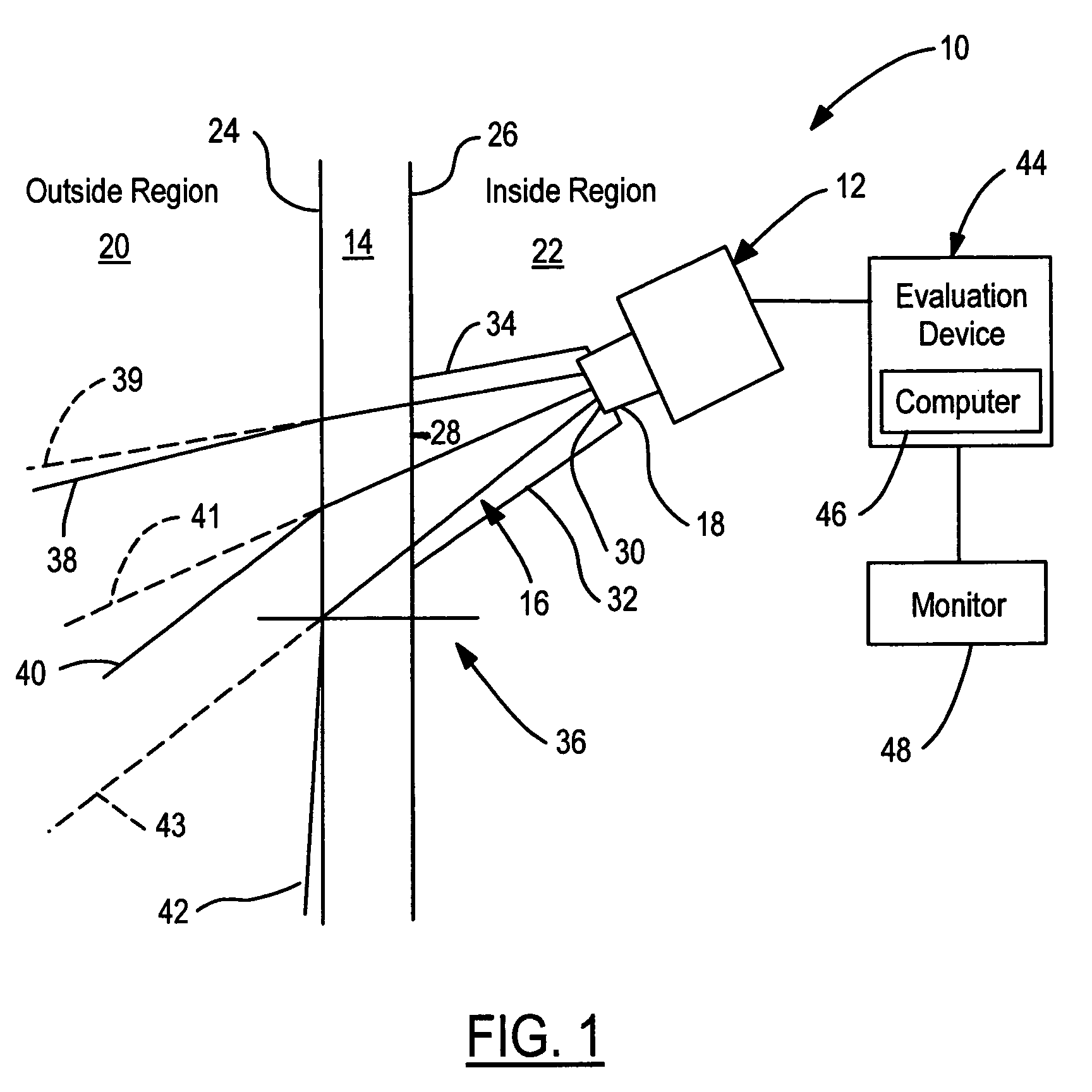
[0016]Referring now to FIG. 1, a schematic representation of a camera arrangement 10 in accordance with an embodiment of the present invention is shown. Camera arrangement 10 includes a camera 12, a pane 14, and a light-guiding element 16. Camera 12 includes a lens 18. Pane 14 separates an outside region 20 from an inside region 22. Pane 14 has an outer surface 24 facing outside region 20 and an inner surface 26 facing inside region 22. Outer and inner surfaces 24, 26 of pane 14 are parallel to one another such that pane 14 is a flat parallel pane. Pane 14 may be a window pane of a vehicle or a building.

[0017]Camera 12 is arranged in inside region 22 with camera lens 18 being oriented in a slanted direction towards pane 14. Light-guiding element 16 is arranged between camera 12 and pane 14. Forward side 28 of light-guiding element 16 is connected to inner surface 26 of pane 14 and opposite rearward side 30 of light-guiding element 16 is connected to camera lens 18. The connections ...


PUM


Abstract

A camera arrangement includes a camera having a lens pointed at a pane and being separated from the pane. A light-guiding element is between the camera lens and the pane. The light-guiding element guides at least light which is incident on the pane in a grazing manner from a direction of incidence to the camera.

Description

CROSS-REFERENCE TO RELATED APPLICATIONS[0001]This is a continuation-in-part of International Application PCT / EP2007 / 000915, published in German, with an international filing date of Feb. 2, 2007, which claims priority to DE 10 2006 005 168.8, filed Feb. 6, 2006; the disclosures of which are both hereby incorporated by reference.BACKGROUND OF THE INVENTION[0002]1. Field of the Invention[0003]The present invention relates to a camera arrangement having a camera directed onto a pane with a light-guiding element being between the camera and the pane.[0004]2. Background Art[0005]A camera arrangement includes a camera and a pane. The pane separates an outside region from an inside region. For example, the pane is a vehicle window pane such that the outside region is the environment outside of the vehicle and the inside region is the vehicle interior. The camera is located in the inside region (i.e., behind the pane) for protection from the outside region and is directed towards the pane t...

Claims


Application Information

Patent Timeline
Patent Type & Authority Patents(United States)
IPC IPC(8): G03B17/00
CPCG03B15/00G03B17/02G08B13/19626G08B13/19647G08B15/001B60R11/04
Inventor BLAESING, FRANKBOEHNE, GREGORNEUMANN, CARSTEN
Owner LEOPOLD KOSTAL GMBH & CO KG
Why Eureka
Try Eureka