Electric powertrain system having bidirectional DC generator

a technology of dc generator and electric powertrain, which is applied in the direction of engine-driven generators, motor/generator/converter stoppers, electric devices, etc., can solve the problems of inefficient utilization of under-hood space, increased fuel costs, and inability to efficiently use the under-hood space. , to achieve the effect of reducing the amount of fuel combusted

Inactive Publication Date: 2010-10-12
CATERPILLAR INC
View PDF21 Cites 52 Cited by
  • Summary
  • Abstract
  • Description
  • Claims
  • Application Information

AI Technical Summary

Benefits of technology

[0010]In another aspect, the present disclosure is directed to a method of operating a machine. The method includes combusting fuel to generate a first mechanical power output, and converting the first mechanical power output to a first DC power output. The method also includes using the first DC power output to propel the machine, and converting a motion of the machine to a second DC power output. The method further includes converting the second DC power output to a second mechanical power output. The second mechanical power output minimizes an amount of fuel combusted.

Problems solved by technology

In addition, fuel costs have risen significantly in recent years.
While the electric powertrain system of the '775 patent may make use of the energy produced by traction motors in a dynamic braking mode, it may be expensive.
The amount and types of electronic components necessary to manufacture these bidirectional converter circuits may make them prohibitively expensive.
Further, because the electric powertrain system of the '775 patent uses an AC generator to convert the mechanical power output of the engine to electrical power, it may inefficiently utilize under-hood space.
Thus, the AC generator of the '775 patent may take up a relatively large amount of space in an associated vehicle.

Method used


Image

  • Electric powertrain system having bidirectional DC generator
  • Electric powertrain system having bidirectional DC generator
  • Electric powertrain system having bidirectional DC generator

Examples


Embodiment Construction

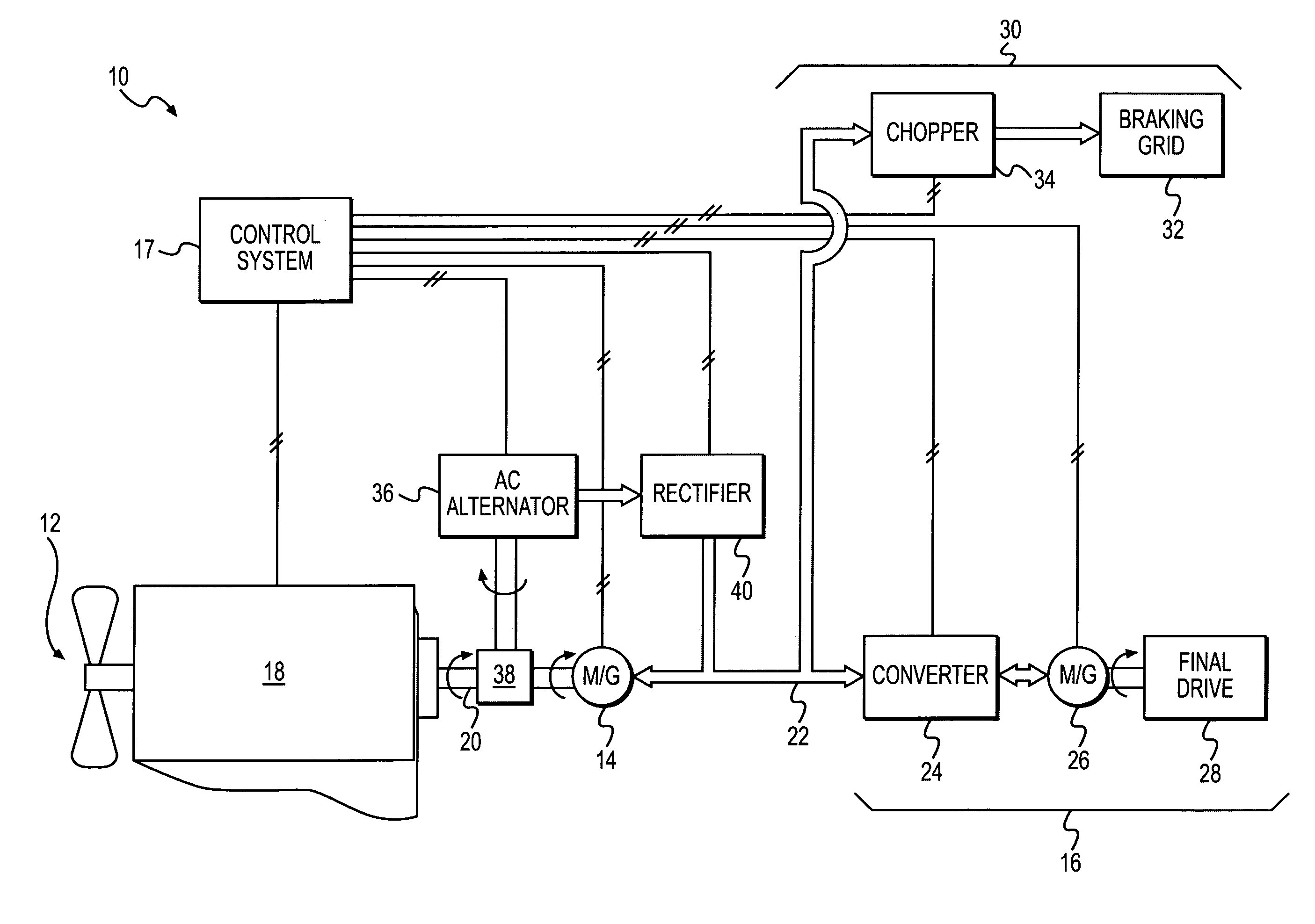
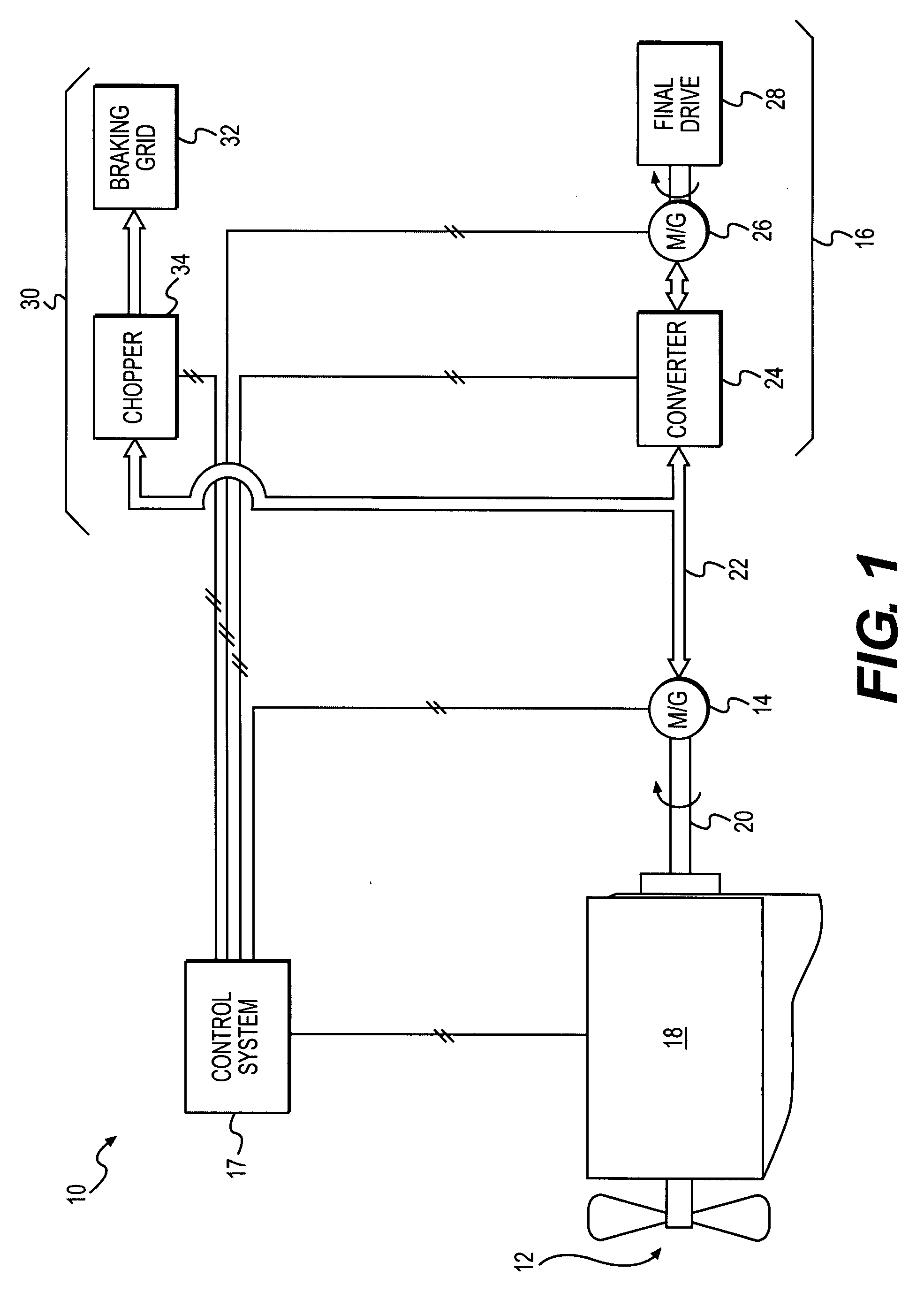
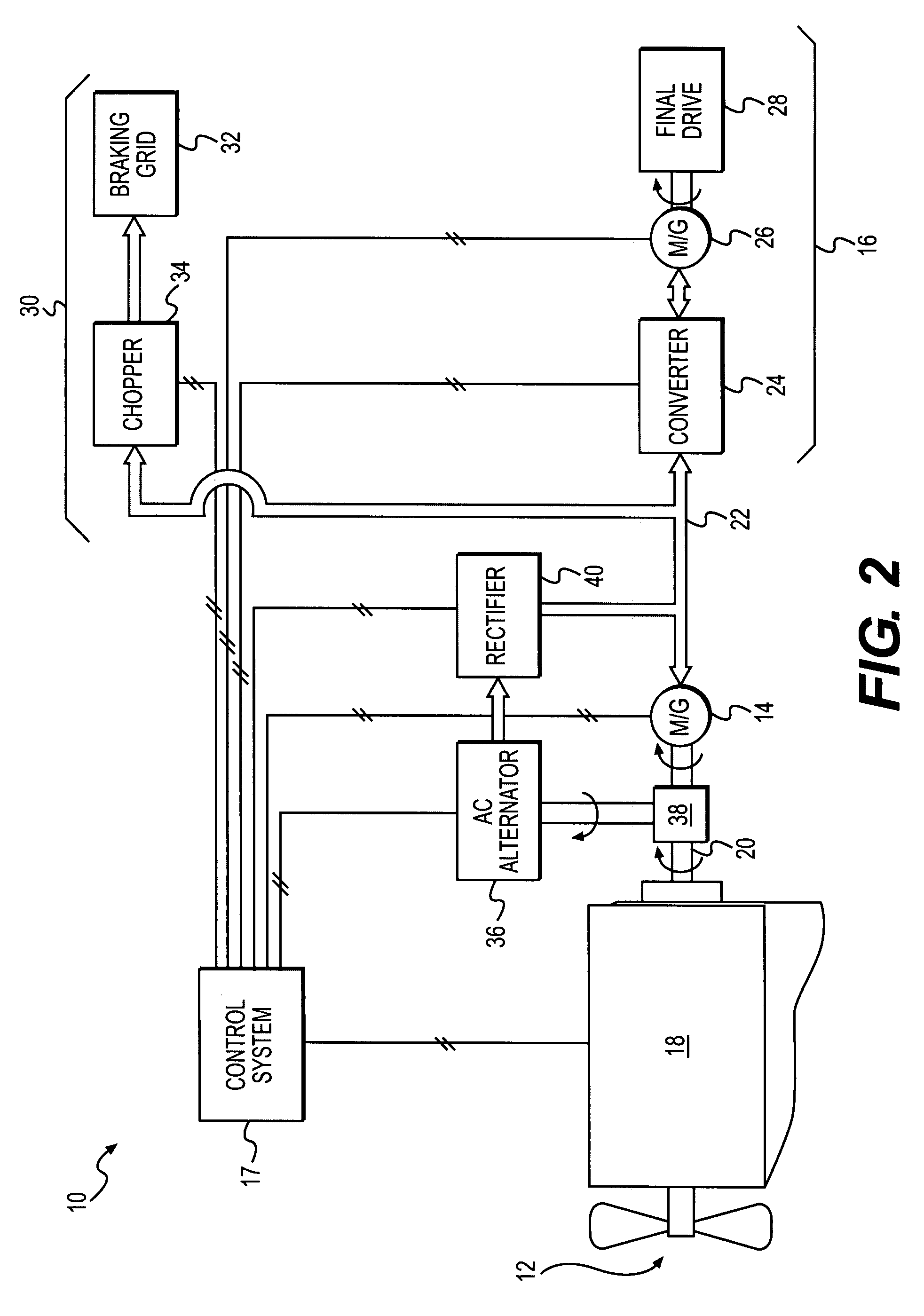
[0013]FIG. 1 illustrates an electric powertrain 10 generally having a power source 12, a DC motor / generator 14, a drivetrain 16, a power dissipation circuit 30, and a control system 17. Powertrain 10 may generally be configured to transfer power in two directions. More specifically, powertrain 10 may be configured to transfer power in a forward direction from power source 12 to drivetrain 16, and in a reverse direction from drivetrain 16 to power source 12.

[0014]Power source 12 may be an internal combustion engine such as, for example, a diesel engine, a gasoline engine, a gaseous fuel-powered engine, or any other engine suitable for driving powertrain 10. Power source 12 may also be a non-combustion source of power such as, for example, a fuel cell, a power storage device, or any other source of power known in the art. Power source 12 may generate a mechanical power output. For example, power source 12 may include an engine block 18 and a crankshaft 20 rotatably disposed within eng...


PUM


Abstract

An electric powertrain for use with an engine and a traction device is disclosed. The electric powertrain has a DC motor / generator operable to receive at least a portion of a first mechanical output from the engine and produce a DC power output. The DC motor / generator is also operable to receive DC power and produce a second mechanical output. The electric powertrain further has a drivetrain operable to receive the DC power output and use the DC power output to drive the traction device. The drivetrain is also operable to generate DC power when the traction device is operated in a dynamic braking mode.

Description

TECHNICAL FIELD[0001]The present disclosure is directed generally to an electric powertrain system and, more particularly, to an electric powertrain system having a bidirectional DC generator.BACKGROUND[0002]Internal combustion engines such as gasoline engines, diesel engines, and gaseous fuel-powered engines exhaust a complex mixture of air pollutants. Due to increased attention on the environment, exhaust emission standards have become more stringent and the amount of pollutants emitted to the atmosphere from an engine is regulated depending on the type of engine, size of engine, and / or class of engine. In addition, fuel costs have risen significantly in recent years. As a result, efforts are being made to produce hybrid electric vehicles with electric powertrain systems that supplement internal combustion engines with electric power to reduce emissions and operating costs (i.e. fuel costs) associated with internal combustion engines.[0003]A typical electric powertrain system for ...

Claims


Application Information

Patent Timeline
Patent Type & Authority Patents(United States)
IPC IPC(8): B60K6/20H02P3/22H02P25/30
CPCB60L11/04B60L2210/20Y02T10/70Y02T10/7077Y02T10/725B60L2220/18B60L50/11Y02T10/7072Y02T10/72
Inventor ADRA, RODWAN TAREK
Owner CATERPILLAR INC
Why Eureka
Try Eureka