

Method for cooling a static electronic power converter device and corresponding device
Active Publication Date: 2010-10-12
INTELLIGENT ELECTRONICS SYST IES
View PDF14 Cites 35 Cited by
- Summary
- Abstract
- Description
- Claims
- Application Information
AI Technical Summary
Benefits of technology
[0010]In a first aspect, the present invention satisfies these objects by providing a method of cooling a static electronic power converter device comprising at least one electrical circuit comprising an assembly of active components and of passive components interconnected in a manner suitable for performing a determined electrical energy conversion function, said circuit including means for inputting electricity that is to be converted and means for outputting converted electricity and being mounted in a closed radiator housing with only said inlet and outlet means of said circuit communicating between the inside of the housing and the outside, the method being characterized in that the distribution of heat energy given off by said active and passive components is made uniform throughout the inside volume of said housing and said heat energy is transferred from said radiator housing by forced convection in substantially uniform manner over the entire inside surface of the walls of said housing, by causing at least one fluid contained inside said leaktight housing to circulate in a closed circuit.
[0025]In another preferred embodiment, the device of the invention includes means for channeling said fluid inside said housing. It can readily be understood that such channeling means serve to guide the flow of air or oil inside the housing, thereby improving fluid circulation and also improving the distribution of the heat that is to be removed in contact with the walls of said housing.
Problems solved by technology
In parallel, said manufacturers and users of electric vehicles require such leaktight converters to be provided at a price that is substantially equivalent to that of converters cooled by forced convection, which means that it is not possible to envisage using expensive technical solutions for making leaktight static electronic power converters that satisfy their requirements, e.g. solutions known in the aviation industry.
Method used
View moreImage
Smart ImageViewing Examples

Examples
first embodiment
[0033]FIG. 5 is a diagrammatic view of a battery charger of the invention in a
second embodiment
[0034]FIG. 6 is a diagrammatic view of a battery charger of the invention in a
third embodiment
[0035]FIG. 7 is a diagrammatic view of a battery charger of the invention in a
Login to View More PUM
 Abstract
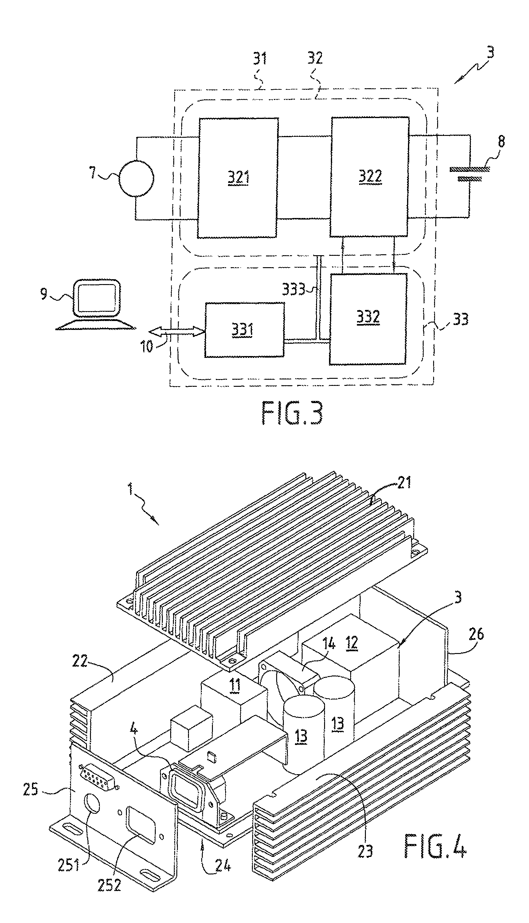
The present invention relates to a method of cooling a static electronic power converter device including at least one electrical circuit including an assembly of active components and of passive components mounted in a closed radiator housing from which only the inlet and the outlet of the circuit communicate with the outside of the housing, in which the distribution of the heat energy given off by the active and passive components is made uniform throughout the inside volume of the housing, and the heat energy is transferred from the radiator housing by forced convection in substantially uniform manner over the entire inside surface of the walls of the housing by causing at least one fluid contained inside the leaktight housing to circulate in a closed circuit. The invention also provides a static electronic power converter device enabling the method to be implemented.
Description
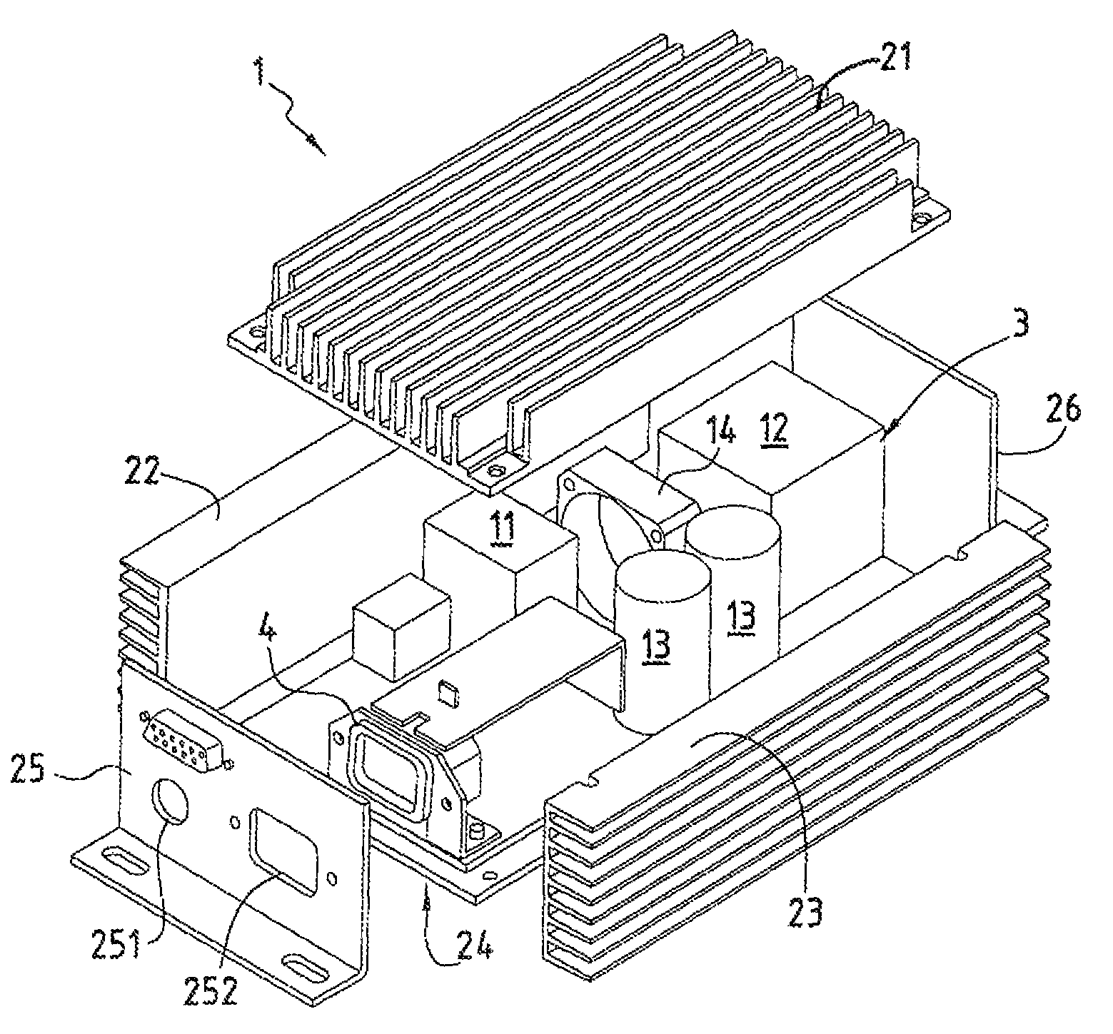
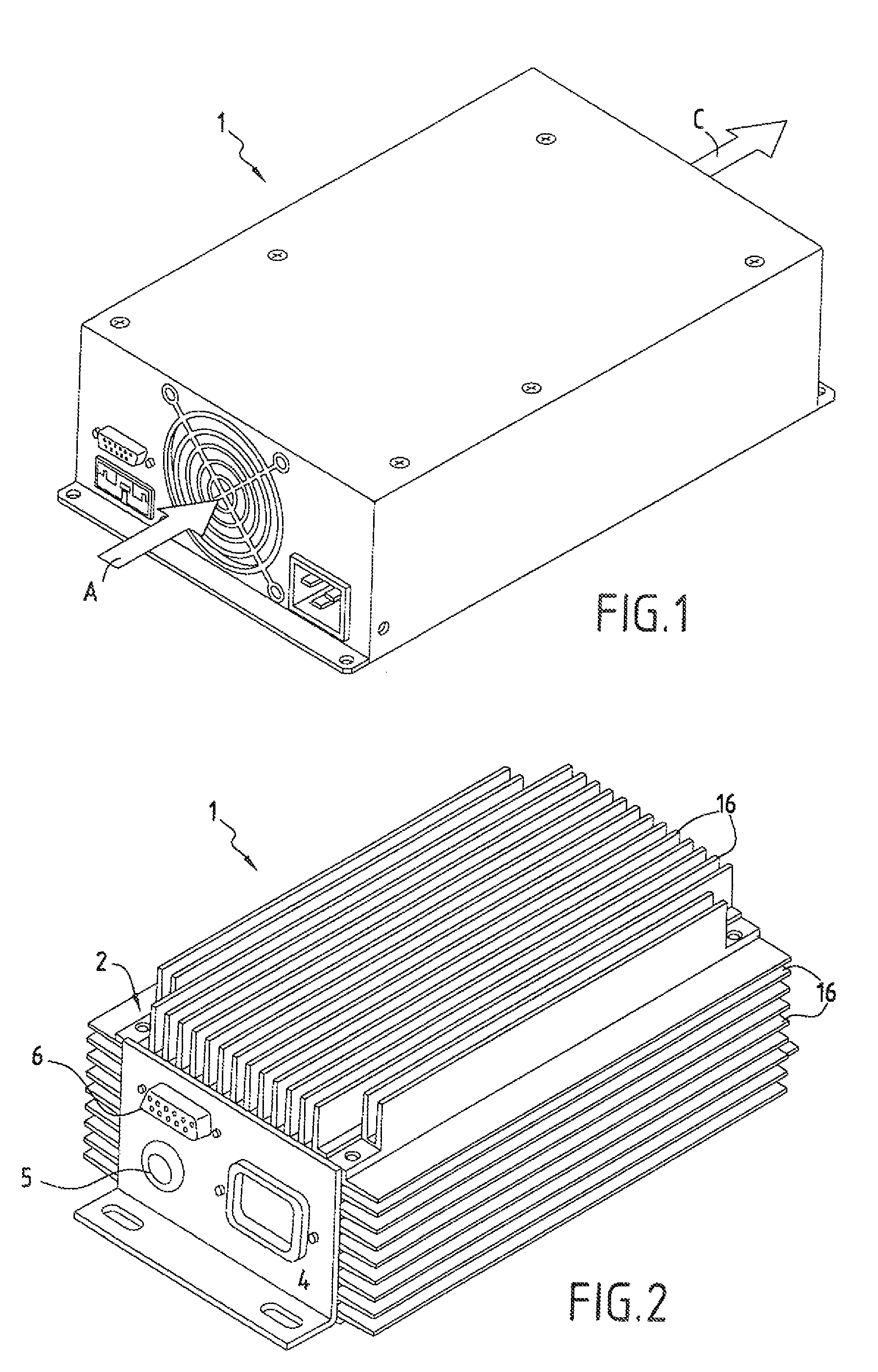
FIELD OF THE INVENTION[0001]The present invention relates to a method of cooling a static electricity converter device and to a corresponding static converter device using the cooling method.[0002]The technical field of the invention is that of designing and fabricating electronic power systems, in particular electricity converters installed in optionally permanent manner in larger mechanical and / or electrical units where they participate in the operation thereof.[0003]Such electricity converter devices apply in particular to on-board battery chargers for electrically powering electric vehicles such as goods transport carriages, elevator pods, or indeed small transport vehicles such as golf carts.[0004]Static converters of the above-described type, e.g. on-board battery chargers, comprise electronic circuits made up of various active electrical components (MOS transistors, diodes) and passive components (transformers, capacitors, inductors, resistors) placed inside metal protective ...
Claims
Login to View More Application Information
Patent Timeline
 IPC IPC(8): H05K7/20
CPCH05K7/20909
InventorMARCHAND, ROGER
OwnerINTELLIGENT ELECTRONICS SYST IES