Low profile attachment hanger system for a cooling liner within a gas turbine engine swivel exhaust duct

a technology of exhaust duct and cooling liner, which is applied in the direction of machines/engines, manufacturing tools, forging/pressing/hammering apparatus, etc., can solve the problems of reducing the overall performance of the engine, reducing reducing the weight of redundant parts, so as to reduce the number of cooling liner segment joints, the effect of reducing maintenance requirements and assembly complications

Inactive Publication Date: 2010-10-19
UNITED TECH CORP
View PDF12 Cites 13 Cited by
  • Summary
  • Abstract
  • Description
  • Claims
  • Application Information

AI Technical Summary

Benefits of technology

[0006]Accordingly, it is desirable to provide a cooling liner assembly for a swivelable exhaust duct which minimizes the number of cooling liner segment joints to increase sealing efficiency while reducing weight, maintenance requirements, and assembly complications.SUMMARY OF THE INVENTION
[0010]The present invention therefore provides a cooling liner assembly for a swivelable exhaust duct which minimizes the number of cooling liner segment joints to increase sealing efficiency while reducing weight, maintenance requirements, and assembly complications.

Problems solved by technology

Since the cooling air is generally extracted from the engine and is then not utilized for producing thrust, this extracted cooling air is a penalty to the overall performance of the engine.
Furthermore, recent aircraft include exhaust ducts which can vector through relative swiveling between exhaust duct segments which are interconnected through bearing arrangements may further complicate cooling liner arrangements.
This may result in a weight and manufacturing penalty for redundant parts, loss of sealing efficiency and a significant number of non-desirable joints between each individual liner segment.

Method used


Image

  • Low profile attachment hanger system for a cooling liner within a gas turbine engine swivel exhaust duct
  • Low profile attachment hanger system for a cooling liner within a gas turbine engine swivel exhaust duct
  • Low profile attachment hanger system for a cooling liner within a gas turbine engine swivel exhaust duct

Examples


Embodiment Construction

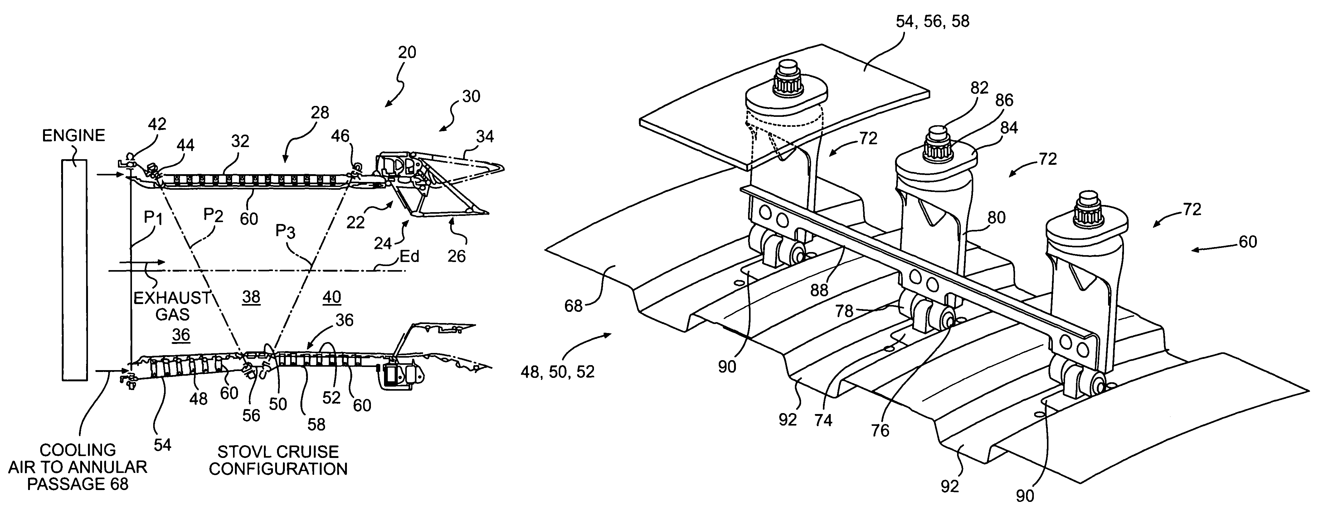
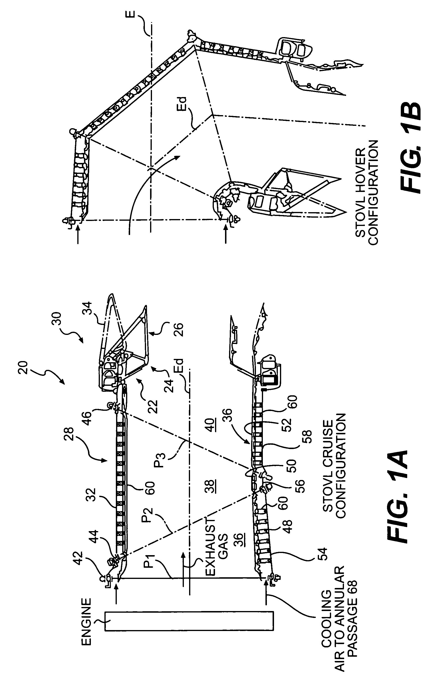
[0030]FIG. 1A illustrates a sectional view of an exhaust duct assembly 20 for a gas turbine engine in both an open position (phantom lines), typical of afterburning operation, and in a closed position (solid lines), typical of non-afterburning operation. In its preferred embodiment this invention is utilized on an exhaust duct assembly that articulate for use in a short take off vertical landing (STOVL) type of aircraft.

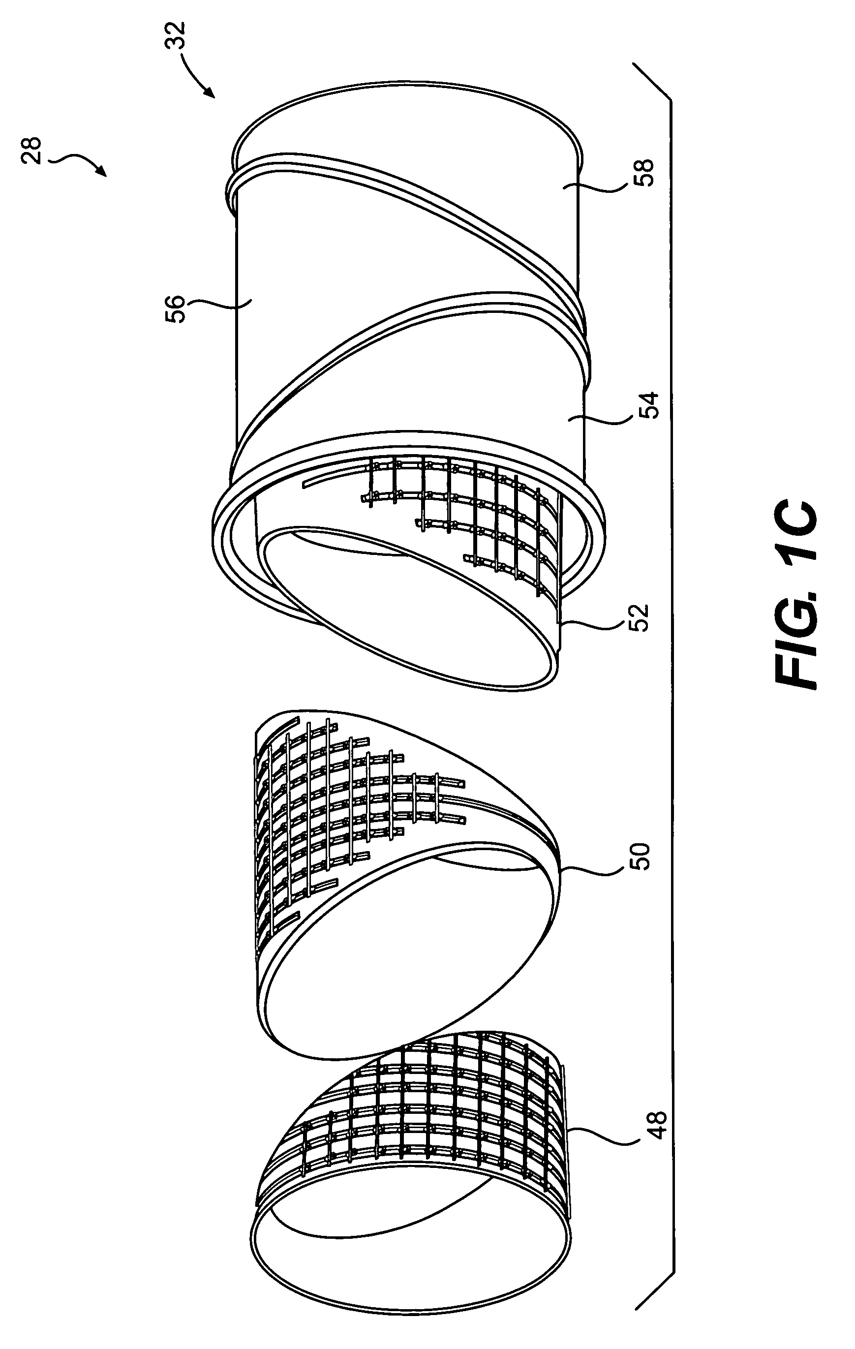
[0031]The exhaust duct assembly 20 is of the convergent-divergent type having a convergent flap region 22, a throat region 24, and a divergent flap region 26. The exhaust duct assembly 20 includes an exhaust duct section 28 which communicates with an exhaust nozzle 30.

[0032]The exhaust duct section 28 as illustrated herein is a three bearing swivel duct (3BSD) which rotates about three bearing planes (P1, P2, P3) to permit transition between a cruise configuration in which the exhaust duct axis Ed is arranged along an engine axis E (FIG. 1A) and a hover configuration...


PUM

PropertyMeasurementUnit
inner diameteraaaaaaaaaa
lengthaaaaaaaaaa
pressureaaaaaaaaaa

Abstract

An exhaust duct assembly includes a cooling liner spaced apart from an exhaust duct case that articulate for use in a short take off vertical landing (STOVL) type of aircraft. The cooling liner assembly is attached to the exhaust duct case through a foldable attachment hanger system. The foldable attachment hanger system provides a low profile (foldable up / down) for a limited access installation envelope typical of a three bearing swivel duct (3BSD) which rotates about three bearing planes to permit transition between a cruise configuration and a hover configuration. In this way, each cooling liner segment may be formed as a complete cylindrical member requiring joints only between the swivelable duct sections.

Description

BACKGROUND OF THE INVENTION[0001]This invention was made with government support under Contract No.: N00019-02-C-3003 with the United States Navy. The government therefore has certain rights in this invention.[0002]The present invention relates to gas turbine engines having a cooling liner, and more particularly to an attachment hanger system for a circumferential cooling liner within a swivelable exhaust duct.[0003]In order to improve engine operation and performance, the usage of exhaust duct cooling air is carefully rationed. Since the cooling air is generally extracted from the engine and is then not utilized for producing thrust, this extracted cooling air is a penalty to the overall performance of the engine. In current gas turbine engine exhaust ducts, a liner is disposed between the engine's working medium (exhaust gas path) and the engine outer casing or duct. Cooling air typically extracted from the engine's compressor is flowed between the cooling liner and duct then disc...

Claims


Application Information

Patent Timeline
Patent Type & Authority Patents(United States)
IPC IPC(8): F02C7/20
CPCF01D25/30F02K1/822Y10T29/49323Y02T50/675F05D2220/90Y02T50/671Y02T50/60
Inventor FARAH, JORGE I.HOOP, WILLIAM G.
Owner UNITED TECH CORP
Why Eureka
Try Eureka