
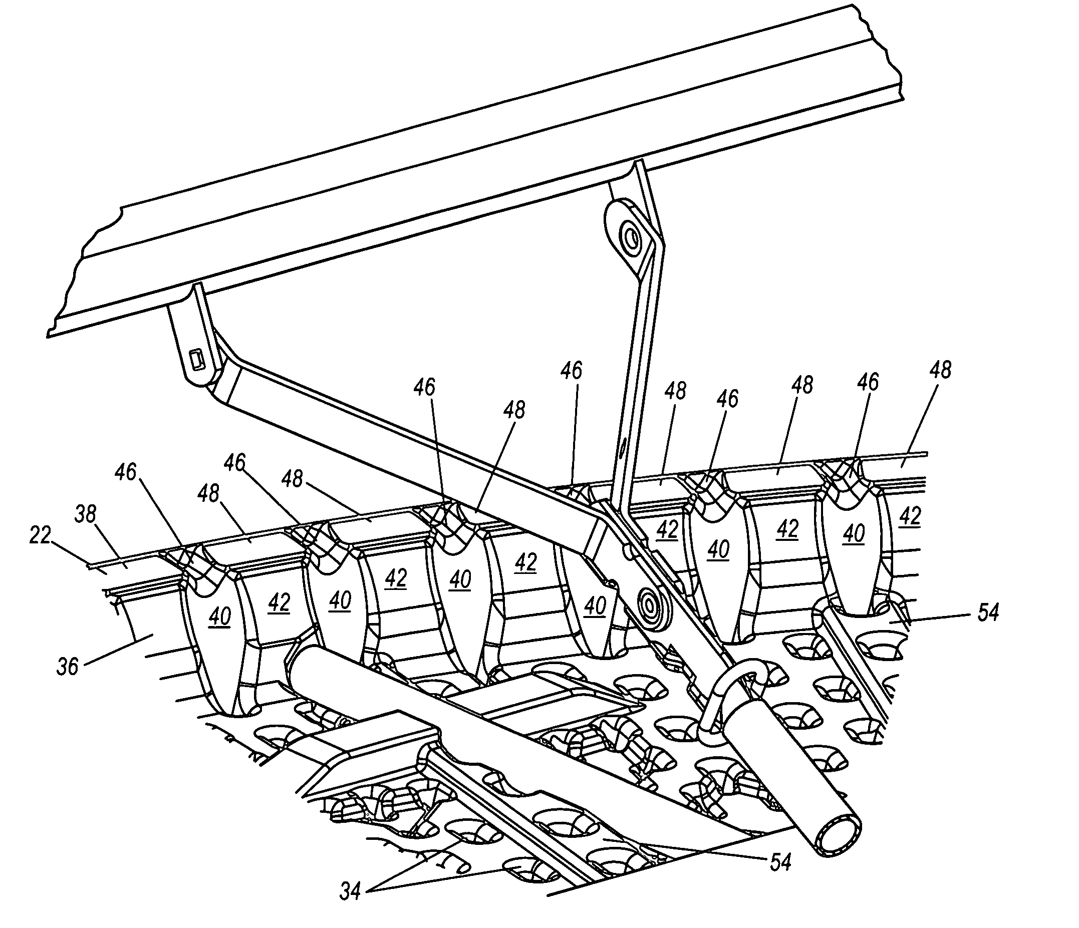
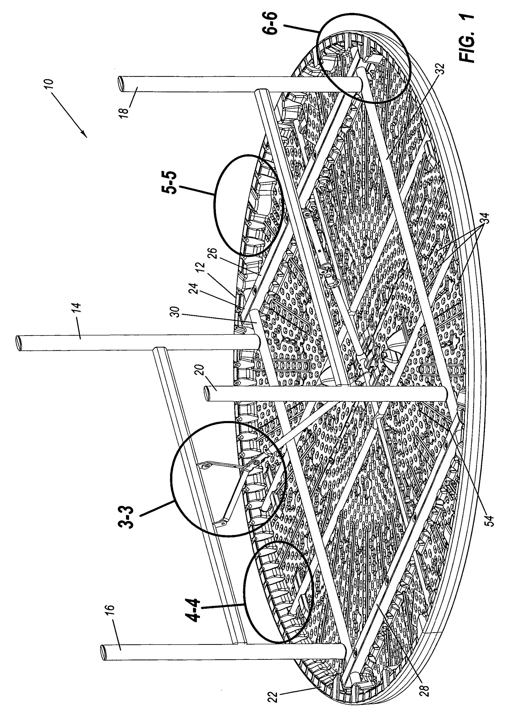
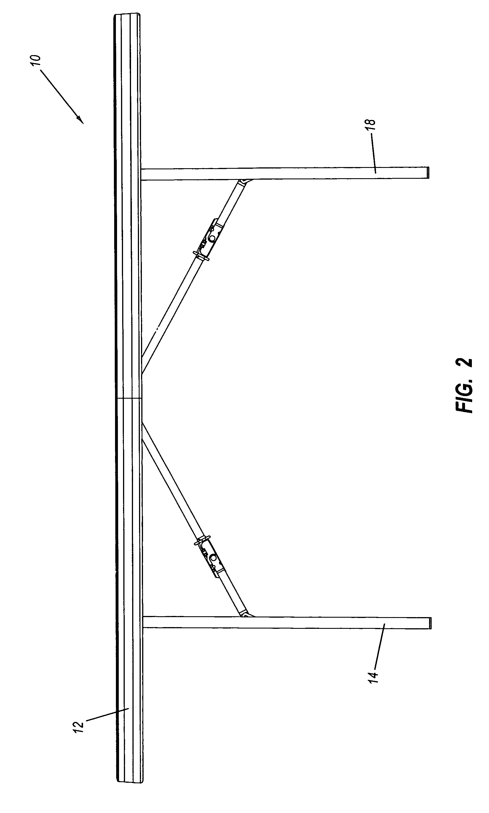
Table with edge support structures

a technology of supporting structure and table top, which is applied in the field of tables with table tops, can solve the problems of reducing the structural integrity of the table top, causing the table to give way and collapse, and creating undesirable stress concentrations in the table top

Inactive Publication Date: 2010-10-19
LIFETIME PRODUCTS
View PDF64 Cites 39 Cited by
  • Summary
  • Abstract
  • Description
  • Claims
  • Application Information

AI Technical Summary

Benefits of technology

The present invention relates to a table with a table top and legs that can be moved between a first position and a second position. The table top is made from plastic, which makes it lightweight. The table top has depressions or "tack-offs" that increase its strength and rigidity. The table also has reinforcement portions on its inner and outer surfaces, which can be raised or lowered. These reinforcement portions can be formed in the table top or the lip of the table. The table can also have one or more depressions or "tack-offs" within the reinforcement portions. The technical effects of this invention include improved strength, resilience, and flexibility of the table top, as well as increased durability and stability of the table.

Problems solved by technology

Disadvantageously, the mechanical fasteners may create a number of holes in the table top and these holes may decrease the structural integrity of the table top and / or create undesirable stress concentrations in the table top.
The holes may also create weakness or failure points that may allow the table to give way and collapse.
The bonding of the legs to the table top, however, may decrease the structural integrity of the table top.
Significantly, if the mechanical fasteners or adhesive connection of the legs to the table top fails, then the table may collapse and the table may be very difficult or impossible to fix or repair, especially if the leg attachment portion of the table top is damaged or pulled away from the remaining portion of the table top.
The use of mechanical fasteners to attach the legs to the table top may undesirably increase the number of parts required to construct the table, which may increase the time required to assemble the table.
This may increase the difficulty of the manufacturing process because the legs and table top must first be held in the desired positions and then the legs must be fastened to the table top.
This process is undesirably time consuming and labor intensive.
Alternatively, a single person may be used to attach the legs to the table top, but this process is difficult to perform rapidly and without any errors.
Many conventional banquet tables are also relatively heavy and difficult to move because of their large size.
The large size and weight of these known tables may require two or more people to move the table.
Many of these lighter-weight tables, however, lack the strength and sturdiness of the heavier-weight tables.
Thus, many lighter-weight tables require complex support mechanisms and one or more support braces to increase the strength and sturdiness of the table, which may undesirably increase the weight and complexity of the tables.
Conventional banquet tables with table tops constructed from plastic may be easily damaged.
For example, if the table is inadvertently knocked over or dropped while being carried, then a portion of the table top may be damaged.
These types of table tops may also be damaged during shipping and / or storage, especially if the tables are stored on their sides or edges.
In addition, conventional banquet tables are frequently dragged or rolled on the ground when being moved, especially if being moved by only one person.
Undesirably, this may damage the outer edge of the table top.
In particular, the edge of the table top may be damaged if the table is rolled down stairs, over curbs or other uneven surface.
If the outer edge of the table top is damaged or crushed, it may be difficult or impossible to repair or replace.

Method used


Image

  • Table with edge support structures
  • Table with edge support structures
  • Table with edge support structures

Examples


Embodiment Construction

[0017]A need therefore exists for a table that eliminates or diminishes the above-described disadvantages and problems.

[0018]One aspect is a table that may include a table top and legs. The legs may be movable between a first position in which the legs extend away from the table top to allow the table to be used and a second position in which the legs are positioned near the table top for storage.

[0019]Another aspect is a table that may include a table top that is constructed from plastic. Desirably, the table top may be constructed from blow-molded plastic and the table top may be lightweight.

[0020]Yet another aspect is a table that may include a table top with one or more depressions, “tack-offs” or “kiss-offs.” The depressions, which preferably extend from one surface towards another surface, are desirably sized and configured to increase the strength and / or rigidity of the table top.

[0021]Still another aspect is a table that may include a table top with a generally downwardly ex...


PUM


Abstract

A table may include a table top that is constructed from blow-molded plastic and the table top may include a generally downwardly extending lip. The lip may include reinforcement portions that are sized and configured to increase the strength, rigidity, resilience and / or flexibility of the lip and / or the table top. The table top may include one or more depressions and the depressions may have different characteristics in different directions. For example, the depressions may have an elongated length and the depressions may have increased strength along its length. Advantageously, the different characteristics of the depressions and / or reinforcement portions may be used to create a table top with increased and / or uniform strength, rigidity, resilience and / or flexibility.

Description

CROSS-REFERENCE TO RELATED APPLICATIONS[0001]This application claims priority to and the benefit of U.S. provisional patent application Ser. No. 60 / 660,061, filed Mar. 9, 2005.[0002]This application is a continuation-in-part of U.S. patent application Ser. No. 10 / 409,273, filed on Apr. 8, 2003, now U.S. Pat. No. 7,111,563; which claims priority to and the benefit of U.S. provisional patent application Ser. No. 60 / 371,486, filed on Apr. 9, 2002.[0003]This application is a continuation-in-part of U.S. patent application Ser. No. 11 / 051,933, filed Feb. 4, 2005, now U.S. Pat. No. 7,475,643; which claims priority to and the benefit of U.S. provisional patent application Ser. No. 60 / 541,639, filed Feb. 4, 2004. U.S. patent application Ser. No. 11 / 051,933 is also a continuation-in-part of U.S. patent application Ser. No. 10 / 409,273, filed on Apr. 8, 2003; now U.S. Pat. No. 7,111,563 which claims priority to and the benefit of U.S. provisional patent application Ser. No. 60 / 371,486, filed o...

Claims


Application Information

Patent Timeline
Patent Type & Authority Patents(United States)
IPC IPC(8): A47B3/00
CPCA47B13/08
Inventor HANEY, THAYNESTRONG, L. CURTIS
Owner LIFETIME PRODUCTS
Learn More