
Method of determining a fire guidance solution

a technology of fire guidance and control solution, applied in the field of determining a fire guidance or control solution, can solve the problems of plurality of values, difficult to use the method in the practical sense, and inability to calculate the projectile flight time and the projectile impact poin

Inactive Publication Date: 2010-10-19
KRAUSS MAFFEI WEGMANN GMBH & CO KG
View PDF5 Cites 0 Cited by
  • Summary
  • Abstract
  • Description
  • Claims
  • Application Information

AI Technical Summary

Benefits of technology

The invention is a method for adjusting a weapon to fire a projectile accurately at a target. The method involves determining the projectile's point of impact and flight times at different angles, and iteratively adjusting the weapon's angle until a firing guidance solution is found. The method takes into account the weapon and target object speeds, and assumes a specific value for a function that describes the optimal angle for firing. The method can be implemented using a movement differential equation solution method and can provide accurate guidance for firing a projectile.

Problems solved by technology

Due to the number and uncertainty of the parameters, it is generally not possible to calculate the projectile point of impact and the projectile flight time.
The drawback for proceeding in this manner is that a plurality of pairs of values must be provided or prescribed for azimuth and elevation until a firing guidance solution is found.
The calculation time thus required for the frequent solution of the movement differential equations makes a practical use of the firing with this method more difficult when an arbitrary relative movement is present between the weapon and the target option.

Method used


Image

  • Method of determining a fire guidance solution
  • Method of determining a fire guidance solution
  • Method of determining a fire guidance solution

Examples


Embodiment Construction

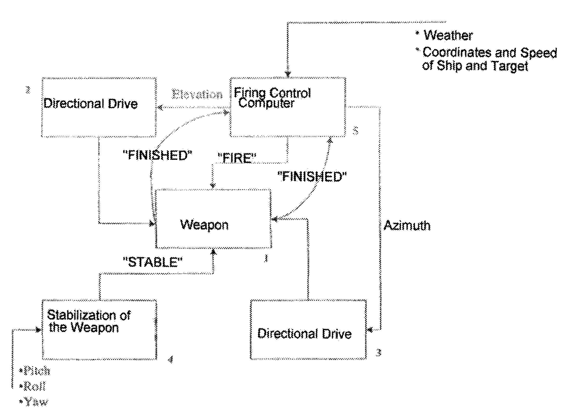
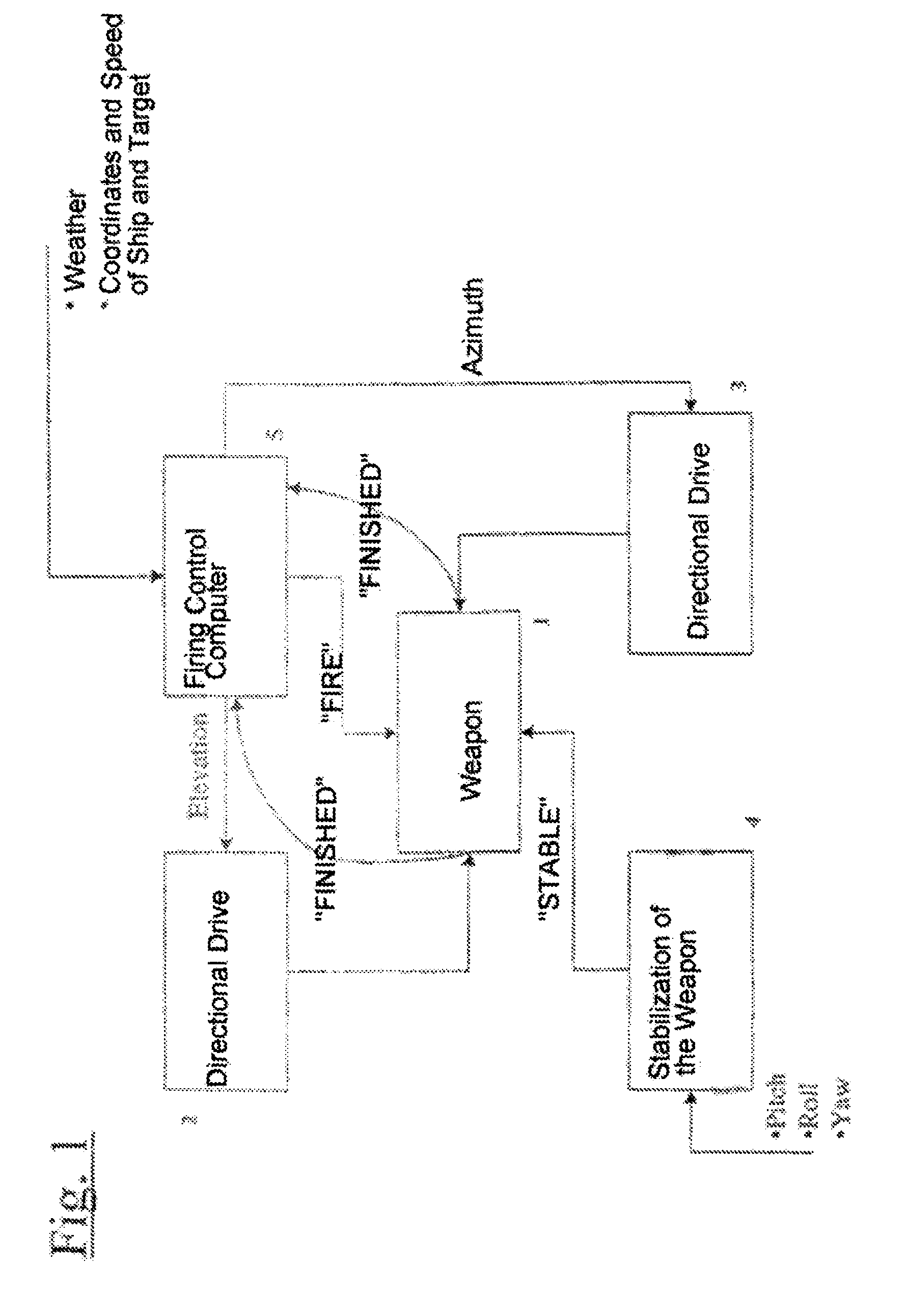
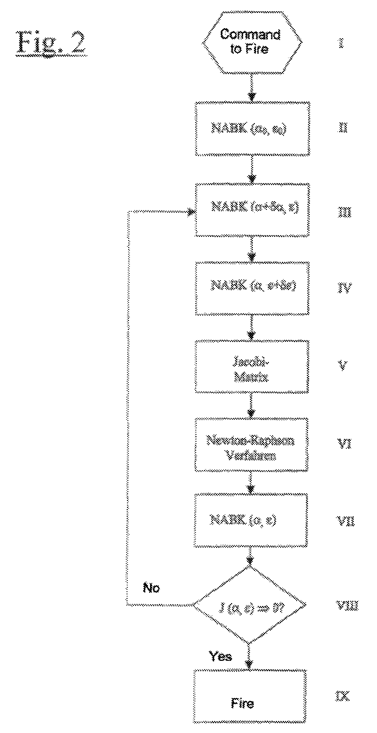
[0020]FIG. 1 schematically illustrates a weapon system, such as is used, for example, on a ship, in addition to the weapon 1, it is provided with an elevation-directional drive 2 and an azimuth-directional drive 3, as well as means 4 to stabilize the weapon. The weapon system is furthermore provided with a firing control computer 5 that controls components of the weapon system. The firing control computer 5 has, among others, the object of determining the firing guidance or control solution, i.e. to determine the values for the azimuth and the elevation angle in such a way that the target object will be hit or struck. The process of determining the firing guidance solution is described in FIG. 2. In the following, the assumption is made that the command to fire was given by a responsible person, and the weapon 1 was loaded.

[0021]The object of the means 4 to stabilize the weapon is to compensate for the influences of the values of pitch, roll and yaw, which are measured by suitable s...


PUM


Abstract

A method of determining a firing guidance solution when relative movement exists between a projectile-firing weapon and a target object that is to be hit, including the steps of adjusting the weapon in azimuth angle and elevation angle, by means of a movement differential equation solution method determining a projectile point of impact and flight times at prescribed azimuth and elevation angle values in view of the ammunition used and external influences, varying the azimuth and elevation angles, as input parameters of the movement differential equation solution method, until a firing guidance solution is found, taking into consideration the weapon and target object speeds, providing a function J (α, ε) that assumes a particular value J* when the azimuth and elevation angles represent a firing guidance solution, and selectively iteratively varying the azimuth and elevation angles using mathematical processes such that the particular value J* is found.

Description

BACKGROUND OF THE INVENTION[0001]The present invention relates to a method of determining a fire guidance or control solution when a relative movement exists between a weapon that fires a projectile, and which is movable in azimuth and elevation, and a target object that is to be hit or struck.[0002]The fire guidance solution refers to the pairs of values of azimuth angle α and elevation angle ε that are to be set and with which the projectile point of impact coincides adequately precisely with the location of the target object at the same point in time after the projectile flight time.[0003]The starting point of the invention is the difficulty of determining the point of impact and the flight time of a projectile that has been fired from a weapon that is movable in azimuth and elevation, i.e. of solving the so-called movement differential equations of the extra ballistic. In this connection, the projectile point of impact and the projectile flight time depend not only on the azimut...

Claims


Application Information

Patent Timeline
Patent Type & Authority Patents(United States)
IPC IPC(8): G06F19/00
CPCF41G3/06F41G3/08F41G3/22F41G5/22
Inventor ROTHE, HENDRIKSCHRODER, SVEN
Owner KRAUSS MAFFEI WEGMANN GMBH & CO KG
Learn More