
Lap joint for prosthetic foot

a prosthetic foot and lap joint technology, applied in the field of prosthetic feet, can solve the problems of increasing the bulk and weight of the prosthesis, not being suitable for some amputees, and the prosthesis being too heavy for some patients

Inactive Publication Date: 2010-10-19
WILSON MICHAEL T
View PDF16 Cites 3 Cited by
  • Summary
  • Abstract
  • Description
  • Claims
  • Application Information

AI Technical Summary

Benefits of technology

"The patent describes a prosthetic foot for attachment to a socket worn by an amputee. The prosthetic foot has a body with a forefoot portion and a heel portion, and at least one attachment member that is conformable to the socket. The attachment member is attached to the bottom of the keel body, which has a length measured from the toe end to the heel end. The prosthetic foot also includes a socket attached to the top side of the keel and adapted to receive a limb of an amputee, wherein the socket contacts no more than 35% of the length of the keel as measured from the heel end. The technical effects of this invention include improved comfort, stability, and a more natural gait for amputees."

Problems solved by technology

However, such energy-storing components may significantly increase the bulk and weight of the prosthesis, which may not be suitable for some amputees.
For instance, additional weight and / or bulk may result in a prosthesis that is too heavy for some patients, such as geriatric patients, very young patients, or other patients who suffer some degree of muscular weakness.
Failure of the connection between the prosthesis and the amputee may result in injury to the amputee and may also necessitate expensive repairs or potentially a complete replacement of the prosthesis.
In such conventional prostheses for Chopart / Lisfranc amputees, the resulting butt joint may be relatively weak since it relies solely upon the glue to hold it together.
However, such a relatively large, rigid connection may detrimentally reduce the flexibility of the prosthetic foot as well as increase the bulk of the prosthetic foot, making it more difficult to wear and fit into a standard shoe or sneaker.

Method used


Image

  • Lap joint for prosthetic foot
  • Lap joint for prosthetic foot
  • Lap joint for prosthetic foot

Examples


Embodiment Construction

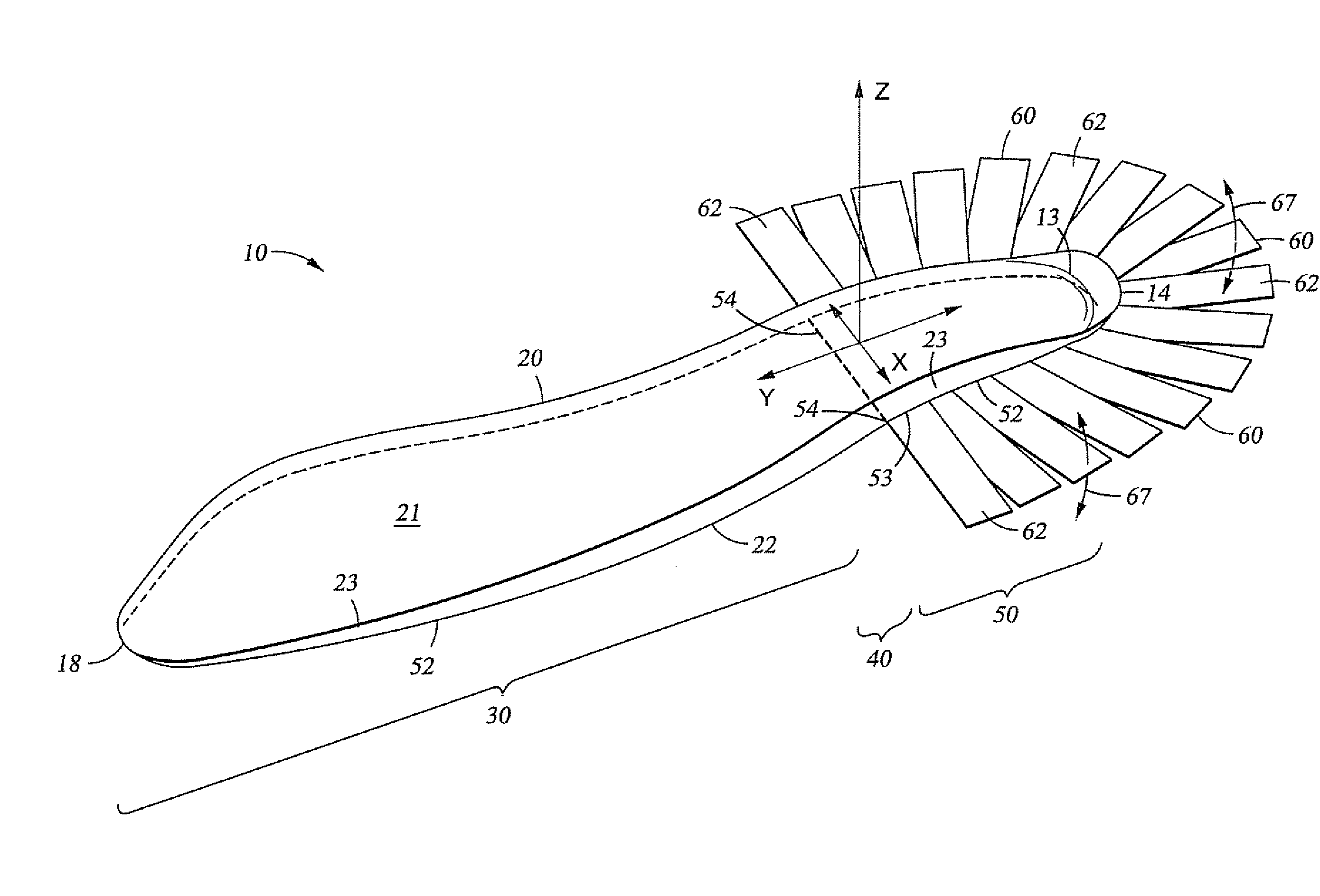
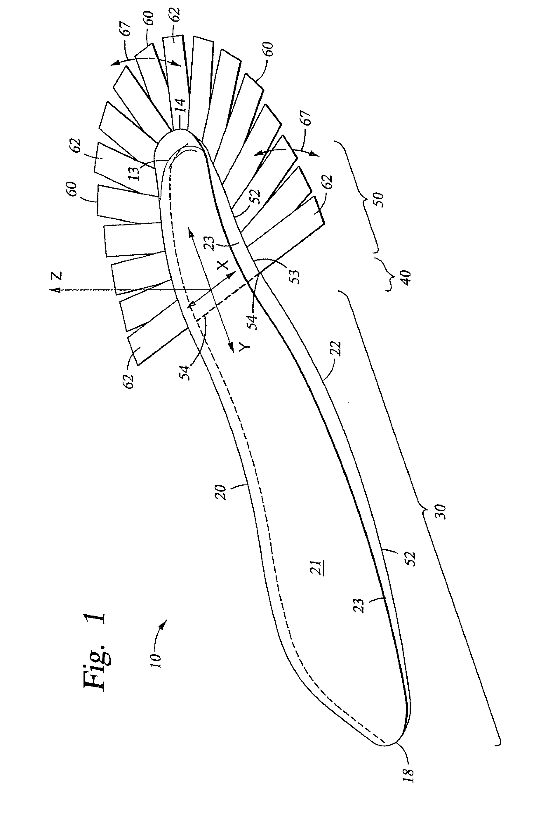
[0013]These and other needs in the art are addressed in one embodiment by a prosthetic foot for attachment to a socket worn by an amputee. In an embodiment, the prosthetic foot comprises a body including a forefoot portion and a heel portion. In addition, the prosthetic foot comprises at least one attachment member extending from the body and conformable to the socket.

[0014]These and other needs in the art are addressed in another embodiment by a prosthetic foot assembly. In an embodiment, the prosthetic foot assembly comprises a keel body having a top surface, a bottom surface, a toe end and a heel end, wherein the keel body has a length measured from the toe end to the heel end. In addition, the prosthetic foot assembly comprises a socket attached to the top side of the keel and adapted to receive a limb of an amputee, wherein the socket contacts no more than 35% of the length of the keel as measured from the heel end.

[0015]These and other needs in the art are addressed in another...


PUM


Abstract

Apparatus and methods for a prosthetic foot for attachment to a socket worn by an amputee. In an embodiment, the prosthetic foot comprises a body including a forefoot portion and a heel portion. In addition, the prosthetic foot comprises at least one attachment member extending from the body and conformable to the socket.

Description

CROSS-REFERENCE TO RELATED APPLICATIONS[0001]Not ApplicableSTATEMENT REGARDING FEDERALLY SPONSORED RESEARCH OR DEVELOPMENT[0002]Not ApplicableBACKGROUND[0003]1. Field of the Invention[0004]The present invention relates generally to a prosthetic foot. More particularly, the present invention relates to a prosthetic foot including a lap joint.[0005]2. Background of the Invention[0006]A useful prosthetic foot should simulate the operation and motion of an anatomical foot. An anatomical foot, including the ankle joint, is capable of motion around three perpendicular axes, as well as varying degrees of flexure. Specifically, the anatomical foot and ankle are capable of dorsiflexion, planiflexion, inversion, eversion, and transverse rotation. Dorsiflexion and planiflexion comprise the movement of the ball of the foot upward and downward, respectively, with respect to the heel. Inversion and eversion are the twisting of the foot around its longitudinal axis, resulting in outward and inward...

Claims


Application Information

Patent Timeline
Patent Type & Authority Patents(United States)
IPC IPC(8): A61F2/68A43B23/28
CPCA61F2/66A61F2/7812A61F2/5046A61F2/80A61F2002/5001A61F2002/5055A61F2002/6642A61F2002/665A61F2002/6685A61F2002/7806A61F2002/7862A61F2310/00017A61F2310/00023A61F2310/00047
Inventor WILSON, MICHAEL T.
Owner WILSON MICHAEL T
Learn More