
Pool chlorinator cell ultrasonic cleaner

a chlorinator cell and ultrasonic cleaner technology, which is applied in the direction of electrochemical machining equipment, crystal growth process, metal-working equipment, etc., can solve the problems of pool water posing a health hazard, time-consuming and expensive routine, pool water may become discolored and unsightly,

Inactive Publication Date: 2010-10-19
MATERIALS & SENSORS TECH
View PDF9 Cites 8 Cited by
  • Summary
  • Abstract
  • Description
  • Claims
  • Application Information

AI Technical Summary

Problems solved by technology

The maintenance of swimming pools, especially in regard to the chemistry of the pool's water, can be a complex, time-consuming and expensive routine.
Unless these factors are carefully controlled, the growth of bacteria and algae in the pool will be excessive with the result that the pool water may pose a health hazard.
In addition, the surfaces of the pool may become discolored and unsightly if the water's chemistry is not controlled.
These acid and chlorine addition steps can be expensive and time consuming for the average pool owner.
While such systems are generally easy to operate, they can occasionally suffer from maintenance problems associated with mineral deposit accumulations on the cell's electrodes.
These maintenance problems can present a drawback to the greater use of such cells in the pool industry.
Prior attempts to resolve this chlorinator cell maintenance problem have provided only limited successes.
However, this approach does not completely eliminate the deposition problem, and it mandates coating on all cell electrodes.
Additionally, failure of cells maintained in this manner has reportedly resulted from erosion of the cell coating.
Although ultrasonic cleaners have been used in a variety of cleaning applications (from cleaning jewelry and medical equipment to micro circuitry and spacecraft parts), they have yet to be effectively used to address the problems associated with the maintenance of submerged electrodes.

Method used


Image

  • Pool chlorinator cell ultrasonic cleaner
  • Pool chlorinator cell ultrasonic cleaner
  • Pool chlorinator cell ultrasonic cleaner

Examples


Embodiment Construction

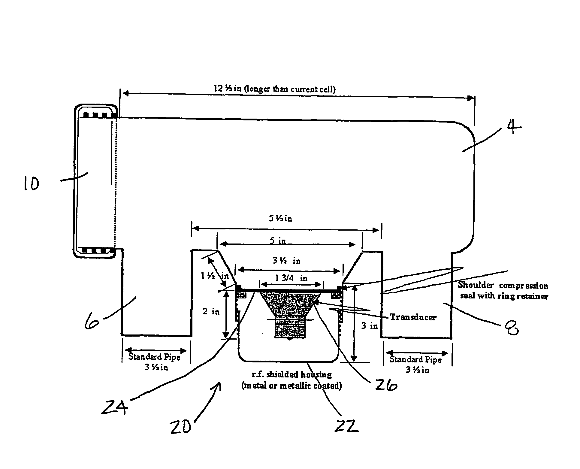
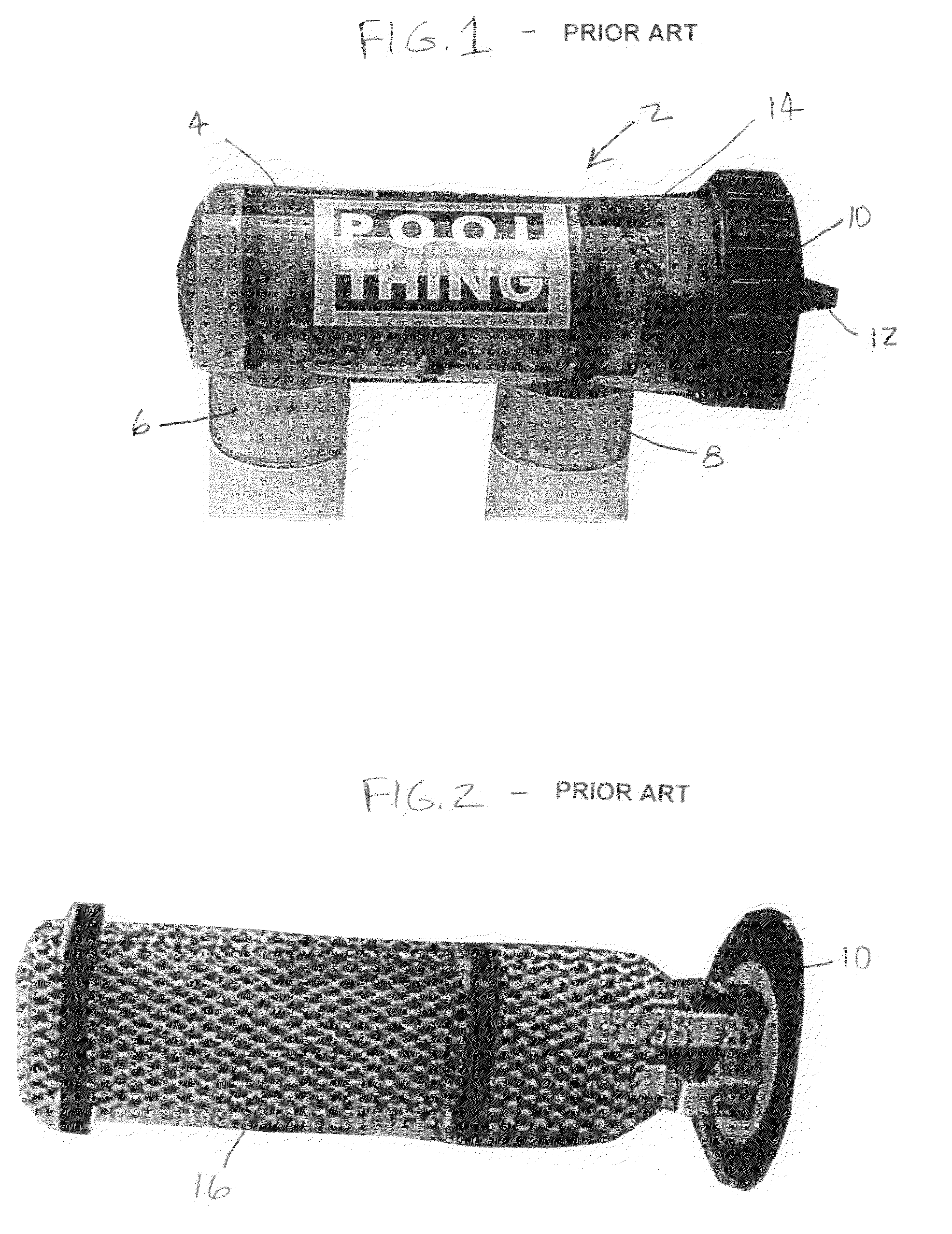
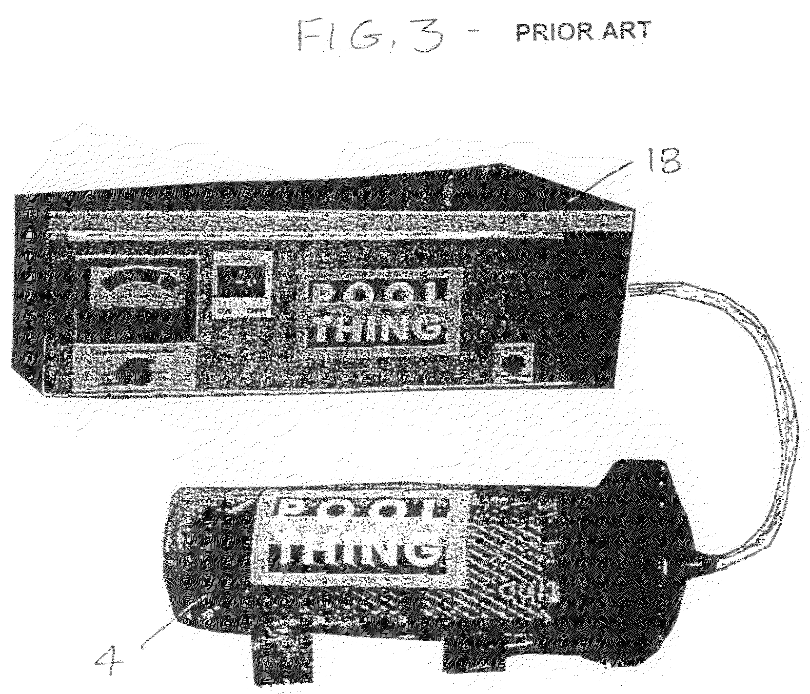
[0037]Before explaining at least one embodiment of the present invention in detail, it is to be understood that the invention is not limited in its application to the details of construction and to the arrangements of the components set forth in the following description or illustrated in the drawings. The invention is capable of other embodiments and of being practiced and carried out in various ways. For example, the preferred embodiments disclosed herein are directed to cleaning and removal of mineral deposits on pool chlorinator cells, but can be applied to other systems that use submerged electrodes which are prone to mineral deposit buildups.

[0038]Also, it is to be understood that the phraseology and terminology employed herein are for the purpose of description and should not be regarded as limiting.

[0039]Furthermore, it should be recognized that the geometry and location of the electrodes and cell shapes described herein can vary dependent on their applications, design freed...


PUM

PropertyMeasurementUnit
frequenciesaaaaaaaaaa
poweraaaaaaaaaa
frequencyaaaaaaaaaa

Abstract

A device for removing mineral deposits from the electrode of a pool chlorinator cell, which has a housing with liquid inlet and outlet ports and in which the electrode is submerged, has: (a) a container having an opening, with this opening being affixed proximate an aperture that is placed in the housing, (b) an ultrasonic membrane which covers the aperture, (c) an ultrasonic transducer mounted in the container and coupled to the membrane in such a manner so as to cause specified, ultrasonic vibrations in the membrane and throughout the liquid contained in the housing, and (d) a frequency modulated power source that drives the transducer. In a preferred embodiment, this device is powered such that the energy projected to the electrodes is in range of 100 to 200 watts and the flux of energy supplied to the membrane is in the range of 4 to 25 watts per square inch of membrane surface area.

Description

CROSS-REFERENCE TO RELATED APPLICATION[0001]This application claims the benefit of U.S. Provisional Patent Application No. 60 / 508,082, filed Oct. 2, 2003 by B. Boro Djordjevic.BACKGROUND OF THE INVENTION[0002]1. Field of the Invention[0003]This invention generally relates to the maintenance and prevention of mineral deposit accumulations on electrodes which are submerged in the chemical baths of electrolytic cells. More particularly, this invention relates to an apparatus and process that uses ultrasonic cleaning to remove mineral deposits that can accumulate on the electrodes of pool chlorination cells.[0004]2. Description of the Related Art[0005]The maintenance of swimming pools, especially in regard to the chemistry of the pool's water, can be a complex, time-consuming and expensive routine. For fresh-water pools, this usually involves, especially during the warmer season, checking the pool's water almost daily to determine and maintain its pH level and chlorine content. Unless t...

Claims


Application Information

Patent Timeline
Patent Type & Authority Patents(United States)
IPC IPC(8): C25B9/00C02F1/467C25B1/26B08B3/12B08B17/00C02F1/36C02F1/461C25B15/00
CPCB08B3/12B08B17/00C02F1/36C02F1/46104C02F1/4674C02F2001/46119C02F2103/42C02F2209/40
Inventor DJORDJEVIC, B. BORO
Owner MATERIALS & SENSORS TECH
Learn More