
Method for remote pre-verification of alarm signals and remote alarm system control

a technology of alarm signals and remote alarm systems, applied in special services, instruments, electrical equipment, etc., can solve problems such as false dispatch, prove to be expensive for all parties involved, and avoid false dispatch

Active Publication Date: 2010-10-19
BRITTON RICK A
View PDF6 Cites 15 Cited by
  • Summary
  • Abstract
  • Description
  • Claims
  • Application Information

AI Technical Summary

Benefits of technology

[0031]It is an object of the invention to provide support in the firmware / software of an electronic, security alarm-system for the transmission of messages directly (or indirectly, as through a service provider) from the alarm control panel to a cell phone (which are presumed to be capable of handling text-based messaging) or other text-messaging device that receives text messages. This thereby allows the user to reply or respond to those messages in a fashion that will affect the way the alarm control panel processes and communicates various alarm signals to the central alarm monitoring station.

Problems solved by technology

This current state of matters proves to be time consuming, costly and cause delays or miss-communication which causes false alarms.
It also proves to be expensive for all parties involved.
This pre-set policy of “assuming the worst case” in many instances results in a false dispatch, when, if the user could have been contacted, then the false dispatch could have been averted.
Now to turn to another matter, currently, remote command of alarm systems is only available through expensive voice modules or software applications that run on computer systems connected through dial-up modems.
This process is cumbersome, inconvenient, and not conducive to the modern lifestyle which is so much on the go and has become treated to these days with so many portable conveniences.

Method used


Image

  • Method for remote pre-verification of alarm signals and remote alarm system control
  • Method for remote pre-verification of alarm signals and remote alarm system control
  • Method for remote pre-verification of alarm signals and remote alarm system control

Examples


Embodiment Construction

[0041]There are shown in the drawing certain exemplary embodiments of the invention as presently preferred. It should be understood that the invention is not limited to the embodiments disclosed as examples, and is capable of variation within the scope of the skills of a person having ordinary skill in the art to which the invention pertains.

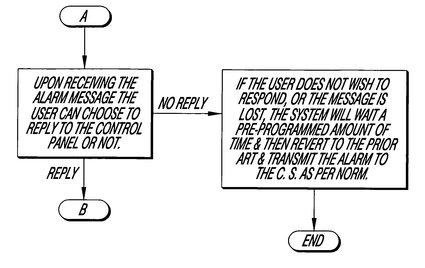
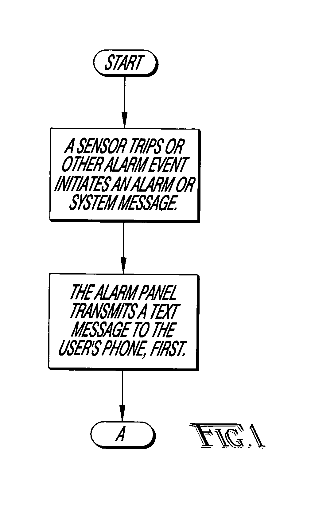
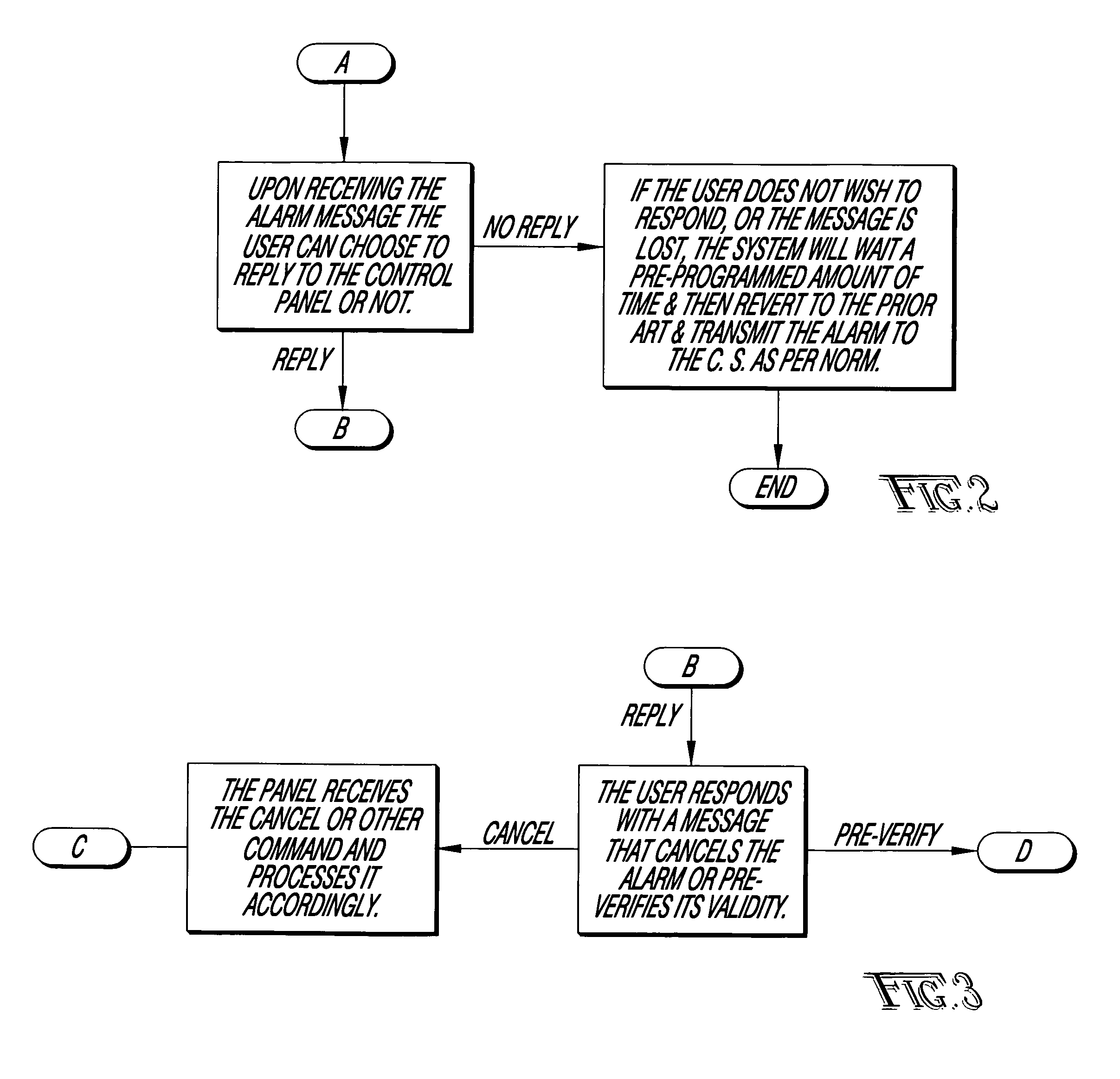
[0042]FIGS. 1 through 6 comprise a set of block diagrams that tile together in ways as indicated by the numbered bubbles and collectively show apparatus and processes in accordance with the invention for carrying out the method in accordance with the invention for remote pre-verification of alarm signals and remote alarm system control.

[0043]A system and method in accordance with the invention comprises the creation and immediate transmission of system events and alarm events to the primary user's cell phone or other text-messaging device. This will allow the primary user to respond with one of many commands in which the response will determine ...


PUM


Abstract

A method of alarm data communication involves protecting a premise with an alarm sensor, sensing an exception, text messaging a responsible user's text-messaging device a text message indicative of such exception and, in the absence of an effective cancel instruction, propagating a signal to a central alarm monitoring station indicative of such exception or otherwise expediting dispatch of authorities to the premise in response to such exception. Another aspect of this method involves that, notwithstanding the absence of an effective cancel instruction, there instead might be the issuance of an effective verify instruction, which propagates to the central alarm monitoring station as indicative of not only the exception but also that such exception is verified.

Description

CROSS-REFERENCE TO RELATED APPLICATION(S)[0001]This application claims the benefit of U.S. Provisional Application No. 60 / 847,982, filed Sep. 28, 2006.[0002]This application is also a continuation-in-part of U.S. patent application Ser. No. 11 / 901,951, filed Sep. 19, 2007, which claims the benefit of U.S. Provisional Application No. 60 / 845,704, filed Sep. 19, 2006; and U.S. Provisional Application No. 60 / 847,982, filed Sep. 28, 2006.[0003]All the foregoing disclosures are incorporated herein by this reference.BACKGROUND OF THE INVENTION[0004]1. Field of the Invention[0005]This invention relates to a user's interaction with an electronic security system and, more particularly, to a provision which provides the user the ability to interact with the alarm system via messaging on a cell phone or other device that receives and sends text messages.[0006]A non-limiting example utilization of the invention includes but is not limited to the pre-verification of alarm signals. Such pre-verifi...

Claims


Application Information

Patent Timeline
IPC IPC(8): G08B23/00
CPCG08B25/001
Inventor HILLENBURG, MARK A.BRITTON, RICK A.HEIRONIMUS, KYLE
Owner BRITTON RICK A
Learn More