MEMS device with an angular vertical comb actuator

a vertical comb actuator and comb actuator technology, applied in the direction of acceleration measurement using interia force, instruments, other domestic articles, etc., can solve the problem of limited useable angular range, insufficient range for next generation devices, and inability to achieve the sub-micron comb finger alignment accuracy that is required

Active Publication Date: 2010-10-19
LUMENTUM OPERATIONS LLC
View PDF19 Cites 17 Cited by
  • Summary
  • Abstract
  • Description
  • Claims
  • Application Information

AI Technical Summary

Problems solved by technology

Major challenges in electro-statically actuated optical micro-electro-mechanical (MEMS) devices is to achieve a relatively high angle of rotation and to lower the actuation voltage, especially in the switching axis, i.e. the “piano” or Y axis.
Parallel plates (PP) electro-static electrodes suffer from pull-in instability, which limits useable angular range; accordingly, parallel plate electrodes for both piano tilt and roll does not provide sufficient range for next generation devices.
However, a major challenge with vertical comb drives is the sub-micron comb finger alignment accuracy that is required for the stability of the actuator.
However, stringent alignment requirements between the two wafers from which the two comb assemblies are formed can considerably complicate the device processing and negatively affect the device yield.

Method used


Image

  • MEMS device with an angular vertical comb actuator
  • MEMS device with an angular vertical comb actuator
  • MEMS device with an angular vertical comb actuator

Examples


Embodiment Construction

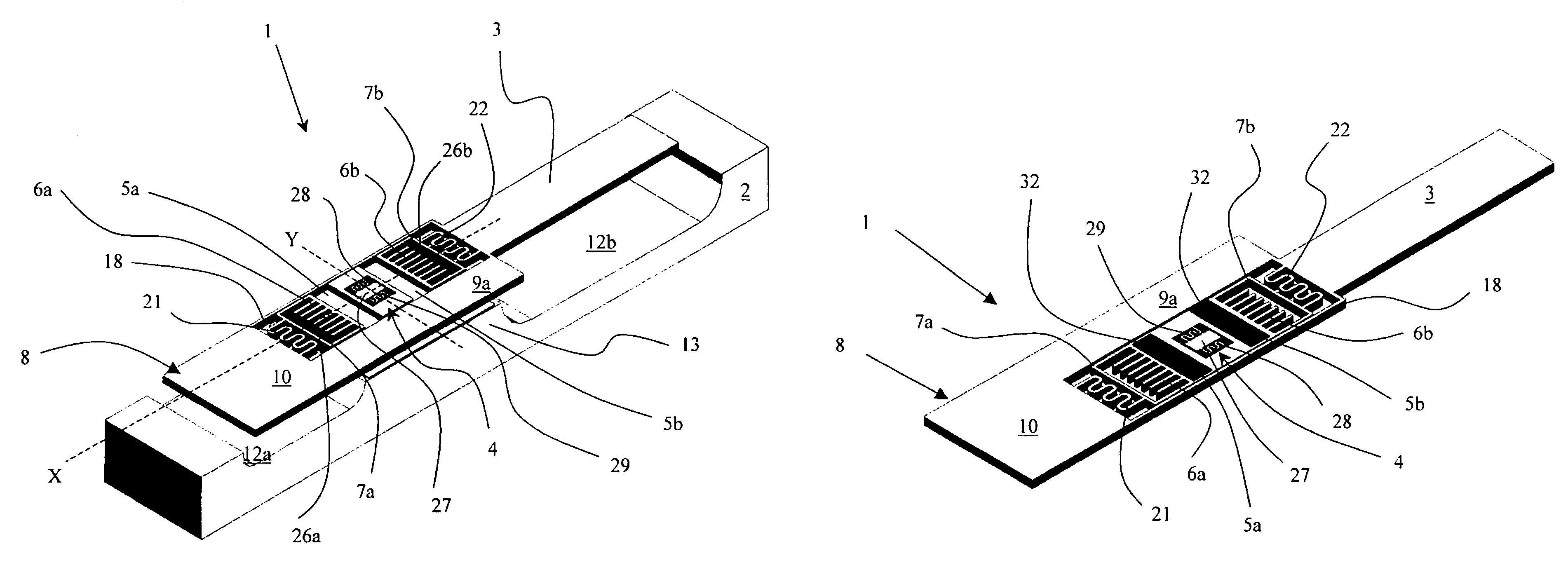
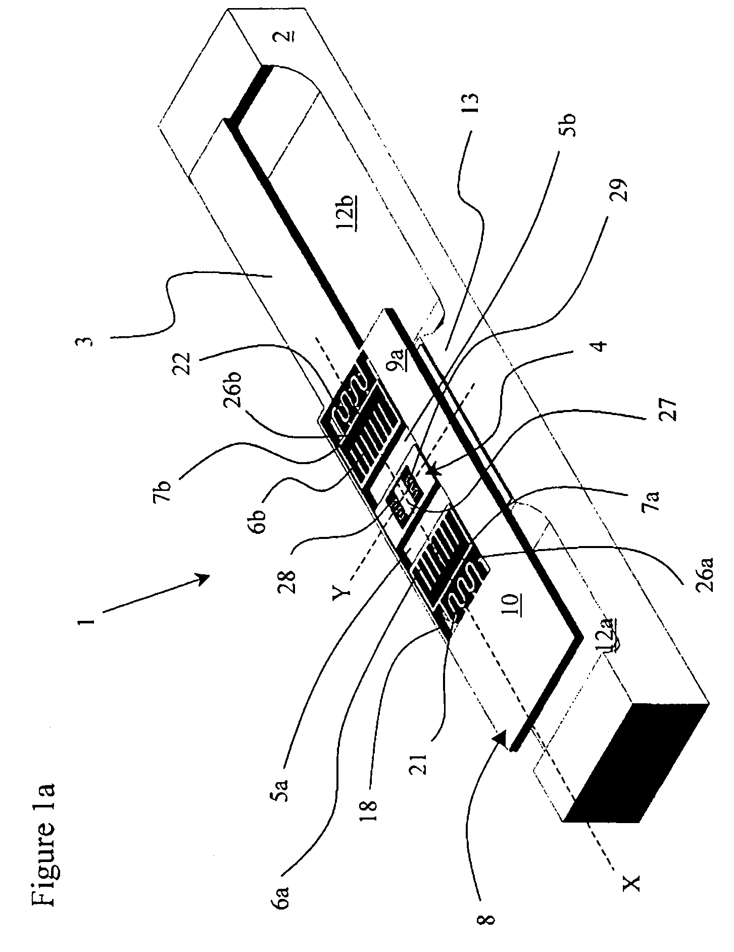
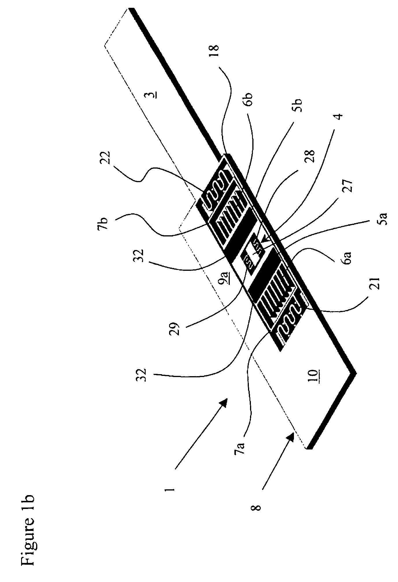
[0033]With reference to FIGS. 1a to 1c the present invention relates to a micro-mirror structure 1, for tilting a platform or deck 8 with a reflective surface 3 about a first lateral switching (Y or tilt) axis above a substrate 2. In the preferred embodiment the reflective surface 3 is also pivotable about a second orthogonal longitudinal rolling axis (X) above the substrate 2; however, micro-mirrors pivoting about a single axis are also within the scope of the invention. The illustrated micro-mirror structure 1 utilizes a hybrid actuator, including an angular vertical comb (AVC) drive for rotating the platform 8 about the switching axis (Y) to obtain a relatively large tilt angle and to reduce the required voltage, and a parallel plate electro-static actuator for rotating the platform 8 about the rolling axis (X); however, the parallel plate electro-static actuator is not necessary for platforms 8 tilling about a single axis.

[0034]An internal frame structure 4 is pivotable about th...


PUM

PropertyMeasurementUnit
temperatureaaaaaaaaaa
thicknessaaaaaaaaaa

Abstract

A vertical comb electro-static actuator for rotating a micro-electro-mechanical micro-mirror device about a tilt axis or rotation. The rotor comb fingers of the comb drive extend from a sub-frame of the micro-mirror, which includes a prestressed layer for bending the rotor comb fingers at an angle to the substrate and mirrored platform, enabling the platform, the hinges, the rotor comb fingers and the stator comb fingers to be formed in the same layer, i.e. the same etching step.

Description

CROSS-REFERENCE TO RELATED APPLICATIONS[0001]The present invention claims priority from U.S. patent application No. 60 / 945,364 filed Jun. 21, 2007, which is incorporated herein by reference.TECHNICAL FIELD[0002]The present invention relates to a micro-electro-mechanical device utilizing a comb actuator, and in particular to an array of optical micro-mirrors that are tillable under the control of an angular vertical comb drive.BACKGROUND OF THE INVENTION[0003]Major challenges in electro-statically actuated optical micro-electro-mechanical (MEMS) devices is to achieve a relatively high angle of rotation and to lower the actuation voltage, especially in the switching axis, i.e. the “piano” or Y axis. Conventional biaxial MEMS devices, such as those disclosed in U.S. Pat. Nos. 6,934,439 issued Aug. 23, 2005 in the name of Miller et al, and 7,095,546 issued Aug. 22, 2006 in the name of Mala et al include two sets of parallel plate electro-static electrodes for both tilt (Y-axis) and roll...

Claims


Application Information

Patent Timeline
Patent Type & Authority Patents(United States)
IPC IPC(8): G02B26/00G02B26/08
CPCB81B3/004B81B2201/033
Inventor MOIDU, ABDUL JALEEL. K.
Owner LUMENTUM OPERATIONS LLC
Why Eureka
Try Eureka