
Staggered Vertical Comb Drive Fabrication Method

a vertical comb drive and fabrication method technology, applied in the direction of electrostatic motors, microstructural device manufacturing, microelectromechanical systems, etc., can solve the problems of affecting the yield of the device, unable to achieve the required alignment, and complicated device processing

Active Publication Date: 2007-10-18
LUMENTUM OPERATIONS LLC
View PDF1 Cites 17 Cited by
  • Summary
  • Abstract
  • Description
  • Claims
  • Application Information

AI Technical Summary

Benefits of technology

[0014]An object of the present invention is to provide a self-aligned method of fabrication of SVCD devices that are free from all or at least some of the above described and other disadvantages of the prior art methods.

Problems solved by technology

However, stringent alignment requirements between the two wafers from which the two comb assemblies are formed can considerably complicate the device processing and negatively affect the device yield.
Failure to achieve the required alignment can impair the actuator performance and / or reliability as a result of failure modes such as electrical breakdown, mechanical interference, and lateral collapse.
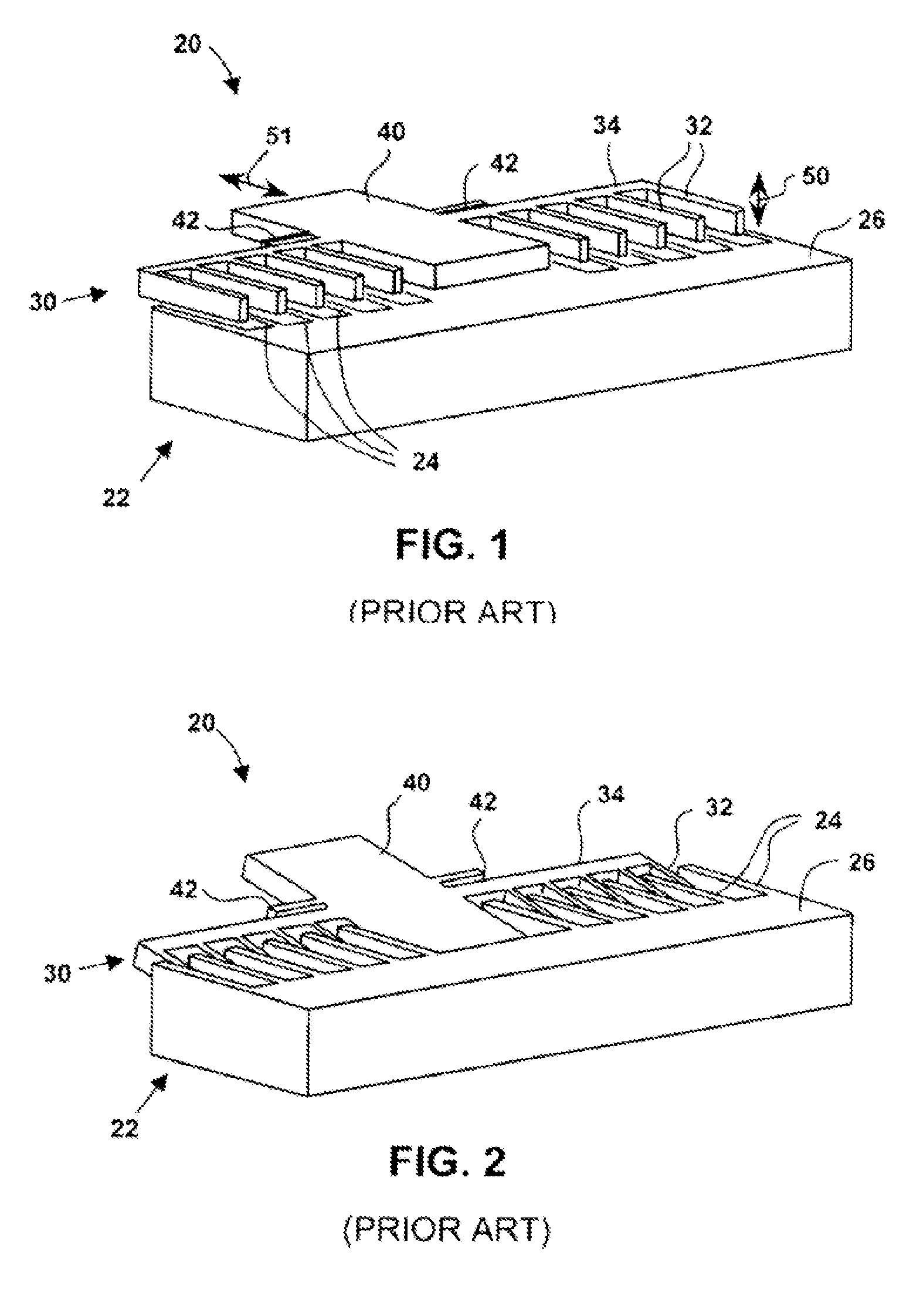
One disadvantage of this method is that the multi-layer fingers it forms may suffer from electrical breakdown at high voltages, which effectively limits the applied voltage and thereby—the rotation angle of the rotor.
This limitation can be especially severe if the oxide layer separating the conducting layers of the fingers is removed, forming the air gap; additionally, the air gap embodiment can be sensitive to the presence of small dust particles, which can electrically shorten the device.
If the oxide layer is not removed, its electrical properties can drift over time; for example, it can accumulate static electrical charge over time altering the electric field coupling the stator and rotor, leading to undesirable variations and / or aging of the device performance.
One disadvantage of the method of Choo et al is that it results in a device with a reduced rotation angle of the rotor, since the applied voltage can only rotate the rotor until a middle point of its fingers is aligned with a middle point of the stator fingers.

Method used


Image

  • Staggered Vertical Comb Drive Fabrication Method
  • Staggered Vertical Comb Drive Fabrication Method
  • Staggered Vertical Comb Drive Fabrication Method

Examples


Embodiment Construction

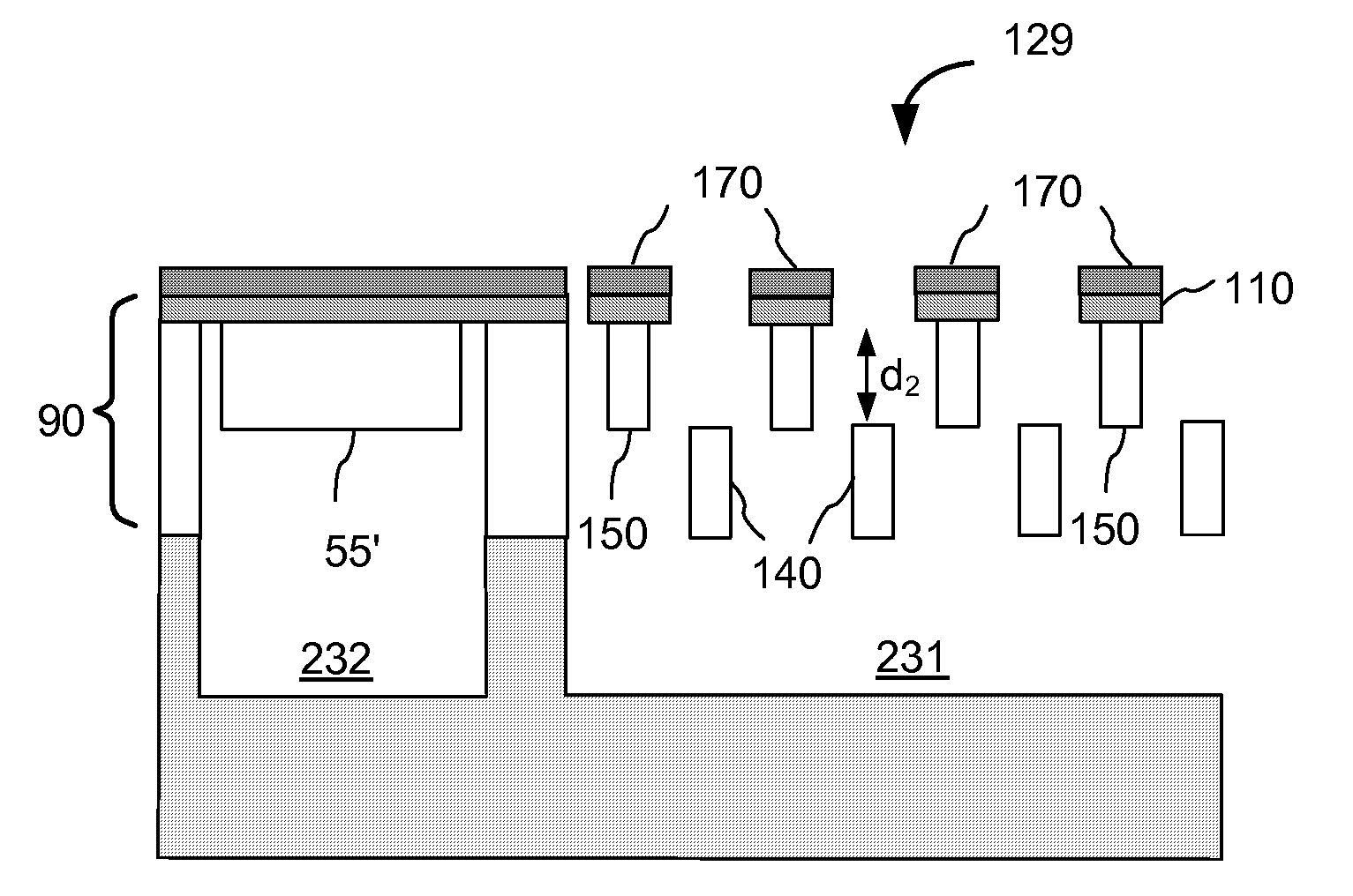
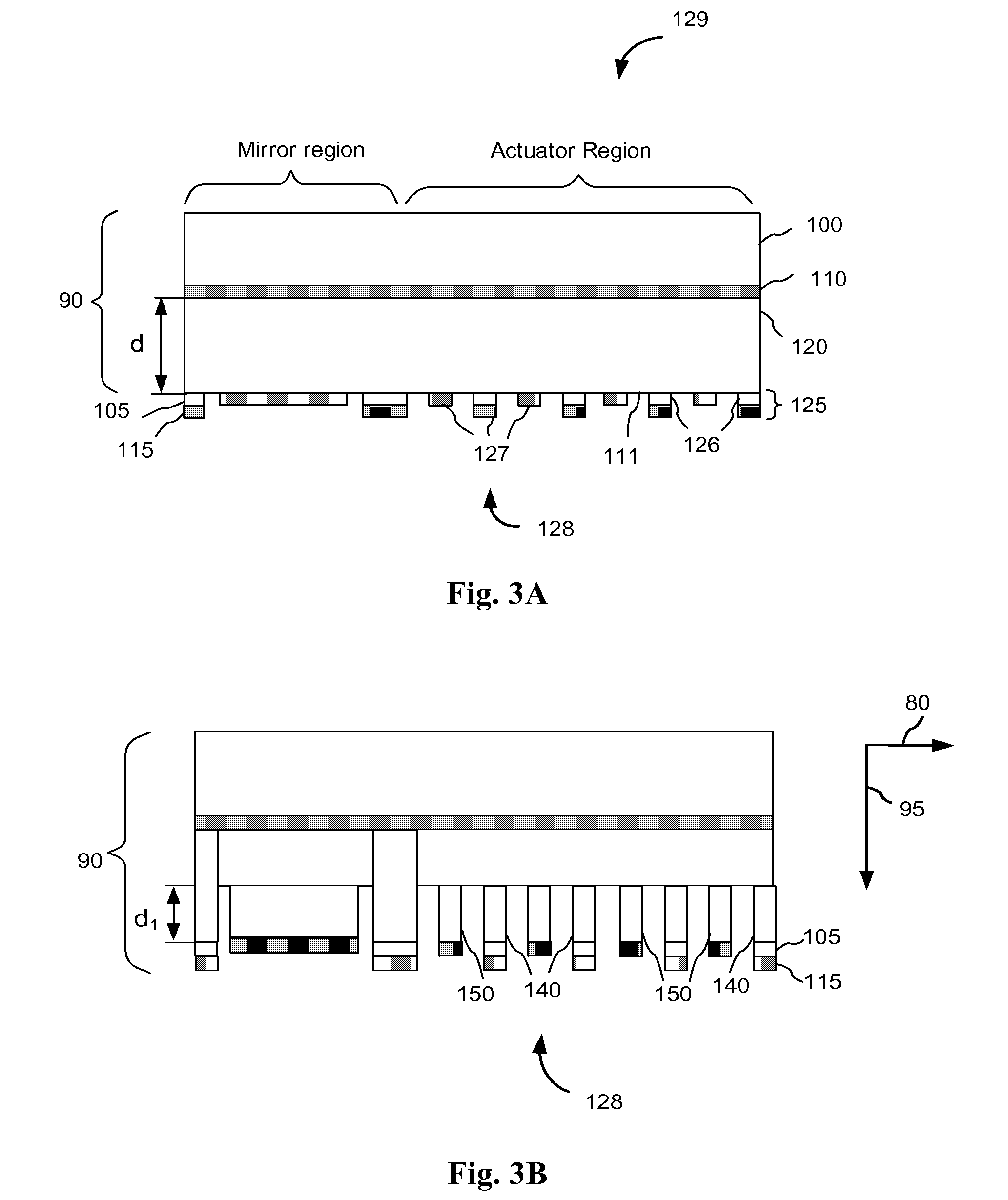
[0027]A preferred embodiment of the method for fabricating an SVCD device according to the present invention is illustrated in FIGS. 3A-3H and is hereafter described with reference to an SVCD device 88, a plane view of which is shown in FIG. 4; FIG. 3I shows an exemplary legend of materials used in the fabrication method of the present invention. One skilled in the art will however appreciate that the method of the present invention can be advantageously employed using a different set of materials, and for fabrication of many other types of SVCD devices having vertically offset features requiring precise lateral alignment.

[0028]As shown in this FIG. 4, the SVCD 88 includes a mirror 55, which is rotatable about torsional hinges 58 anchored by anchor posts 53. The mirror 55 is coupled to a movable comb assembly 60, hereinafter referred to as the rotor 60, which has a set of comb teeth, hereinafter referred as fingers 70. The rotor fingers 70 are positioned in-between fingers 75 of a s...


PUM


Abstract

The invention relates to a method of fabrication of staggered vertical comb drive actuators with relaxed lateral alignment tolerances. A device layer of a wafer is first etched from a front side using a self-aligned two-layer mask to define interdigited fingers of both moving and stationary combs. A second etch step is used for vertically thinning one of the two sets of fingers by selectively removing their top portions. The front side of the wafer is then bonded to a carrier wafer. The wafer is then selectively etched from the back side of the device layer so as to remove lower portions of the second set of fingers, thereby forming interdigited moving and stationary combs having vertically offset fingers.

Description

CROSS-REFERENCE TO RELATED APPLICATIONS[0001]The present invention claims priority from U.S. Provisional Patent Application No. 60 / 791,346 filed Apr. 12, 2006, entitled “Staggered Vertical Comb Drive Fabrication Process with Relaxed Alignment Tolerance”, which is incorporated herein by reference.TECHNICAL FIELD[0002]The present invention relates generally to vertical comb drive actuators and to methods of fabrication thereof, and more particularly to a method of fabrication of an efficient vertical staggered comb drive actuator with improved alignment tolerances.BACKGROUND OF THE INVENTION[0003]A staggered vertical comb drive (SVCD) is a type of MEMS (Micro-Electro Mechanical Systems) actuator capable of relatively high actuator strength and a high speed using electrostatic principal of operation. Furthermore, they can be fabricated using standard materials and scalable processes developed in the semiconductor industry. SVCDs can be advantageously used to control high-speed, high-re...

Claims


Application Information

Patent Timeline
IPC IPC(8): C23F1/00
CPCB81B2201/033B81B2201/042H02N1/008B81C1/00174B81B2203/058
Inventor MOFFAT, STEVEN H.MILLER, JOHN M.
Owner LUMENTUM OPERATIONS LLC
Learn More