Rotary-type comb-drive actuator and variable optical attenuator using the same

a comb-drive actuator and variable technology, applied in the direction of device details, instruments, device details, etc., can solve the problems of increasing the size of elements and the cost of products, products using the actuator, and generating response variations

Inactive Publication Date: 2005-12-01
SAMSUNG ELECTRO MECHANICS CO LTD
View PDF12 Cites 17 Cited by
  • Summary
  • Abstract
  • Description
  • Claims
  • Application Information

AI Technical Summary

Benefits of technology

[0018] Accordingly, the present invention has been made keeping in mind the above problems occurring in the prior art, and an object of the present

Problems solved by technology

However, such a comb-drive scheme requires little current, but requires a high voltage to enhance a driving force.
That is, in order to generate a constant displacement, a high voltage is required, so that a voltage amplification circuit must be separately constructed to control the high voltage using typical digital signals with a voltage of 5V or lower, thus increasing the sizes of elements and costs of products.
However, when the comb-drive actuator is designed and manufactured using the conventional structure, the design of products using the actuator is limited in that, since experimental results show that a resonant frequency is lower than 250 Hz (the number of comb-shaped electrodes is increased eight times and stiffness is decreased by half), response variations are generated depending on exter

Method used


Image

  • Rotary-type comb-drive actuator and variable optical attenuator using the same
  • Rotary-type comb-drive actuator and variable optical attenuator using the same
  • Rotary-type comb-drive actuator and variable optical attenuator using the same

Examples


first embodiment

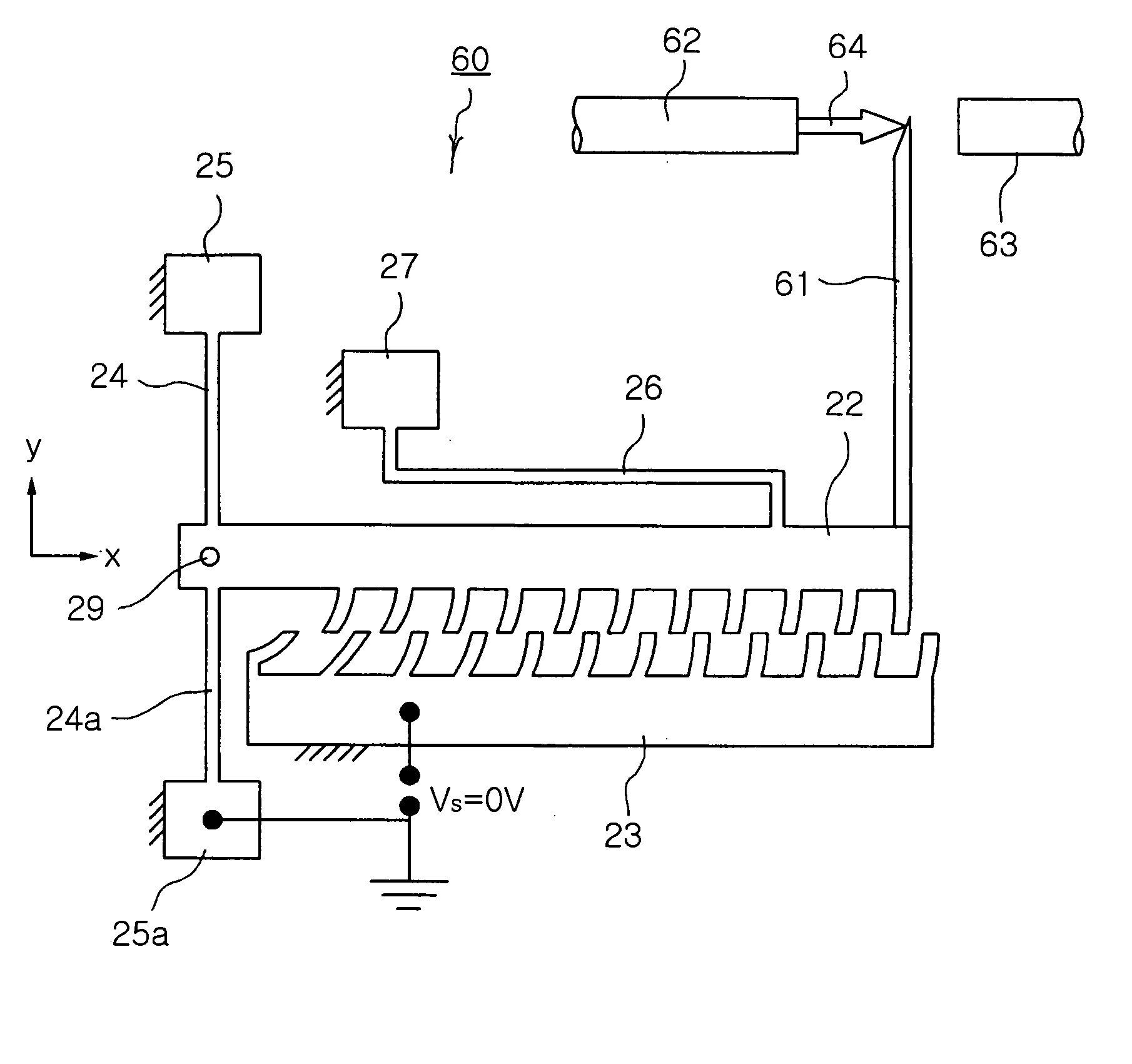
[0038]FIG. 2 is a perspective view of a rotary-type comb-drive actuator according to the present invention.

[0039] Referring to FIG. 2, a rotary-type comb-drive actuator 20 according to the first embodiment of the present invention includes a silicon substrate 21, a comb-shaped movable electrode 22, a comb-shaped drive electrode 23, vertical and horizontal springs 24, 24a and 26, and anchors 25, 25a and 27 to support the springs 24, 24a and 26, respectively.

[0040] The movable electrode 22 is arranged on the silicon substrate 21 to be movable in parallel to the plane of the substrate 21 while being spaced apart from the substrate 21 by a predetermined distance. Further, the movable electrode 22 is formed lengthwise in a horizontal direction, and has the comb-shaped electrode that is formed thereon and comprised of a plurality of fingers to be driven by an electrostatic force.

[0041] The drive electrode 23 has the comb-shaped electrode that is formed thereon and comprised of a plurali...

second embodiment

[0052]FIG. 4 is a plan view of a rotary-type comb-drive actuator according to the present invention.

[0053] Referring to FIG. 4, a rotary-type comb-drive actuator 40 according to the second embodiment of the present invention further includes an auxiliary horizontal spring 41, which is a beam spring arranged in a horizontal (x axis) direction, and an auxiliary horizontal spring anchor 42. The auxiliary horizontal spring anchor 42 is fixed on the substrate 21 by a silicon oxide film 43.

[0054] The rotary-type comb-drive actuator 40 includes the auxiliary horizontal spring 41 extending along the longitudinal direction of the movable electrode 22 from an end of the movable electrode 22 adjacent to the rotation center 29, and the auxiliary horizontal spring anchor 42 to support the auxiliary horizontal spring 41, thus restricting the movement of the movable electrode 22 in the horizontal (x axis) direction through much higher stiffness.

[0055] Further, in the rotary-type comb-drive actua...

third embodiment

[0056]FIG. 5 is a plan view of a rotary-type comb-drive actuator according to the present invention.

[0057] Referring to FIG. 5, a rotary-type comb-drive actuator 50 according to the third embodiment of the present invention further includes a counter mass 51 on a side opposite to the movable electrode 22 around the rotation center 29. The counter mass 51 has a certain weight to allow the rotation center 29 to be the center of the gravity without being fixed on the substrate 21.

[0058] When the counter mass 51 is formed in the rotary-type comb-drive actuator 50 as in the case of the third embodiment of the present invention, the excitation force of a vibration noise acts on the center of the gravity, that is, the rotation center 29, even when the vibration noise is externally caused in any direction of translational motion, thus eliminating moment generated in the actuator 50 by such excitation. The rotary-type comb-drive actuator 50 having the counter mass 51 can minimize the genera...


PUM


Abstract

The present invention relates to an actuator and optical attenuator using the actuator. The rotary-type comb-drive actuator includes a substrate, a movable electrode, a drive electrode, one or more vertical springs, one or more vertical spring anchors, a horizontal spring and a horizontal spring anchor. The movable electrode is arranged on a plane of the substrate to be movable in parallel to the substrate plane, and formed to have a predetermined length so as to have a comb-shaped electrode comprised of a plurality of fingers. The drive electrode is formed to have a length corresponding to that of the movable electrode, and formed to have a comb-shaped electrode that is comprised of a plurality of fingers and arranged to be interdigitated with the comb-shaped electrode of the movable electrode. The vertical springs are arranged in parallel to the substrate, and connected to be perpendicular to the movable electrode on both sides of a first end of the movable electrode. The vertical spring anchors are connected to the vertical springs to support the vertical springs. The horizontal spring has a main part connected in parallel to a longitudinal direction of the movable electrode. The horizontal spring anchor is connected to the horizontal spring to support the horizontal spring, and fixed on the substrate.

Description

BACKGROUND OF THE INVENTION [0001] 1. Field of the Invention [0002] The present invention relates, in general, to an actuator provided by micro electro mechanical systems technology and optical actuator using the actuator and, more particularly, to an actuator and optical attenuator using the actuator, which utilizes an attractive force applied between comb-shaped electrodes. [0003] 2. Description of the Related Art [0004] Generally, a comb-drive actuator refers to an actuator in which electrodes each having a plurality of fingers are interdigitated with each other and the positions of the electrodes can be changed using a voltage applied to the two electrodes. [0005] Especially, a comb-drive actuator utilizing Micro Electro Mechanical Systems (MEMS) technology is excellent in the generation efficiency of an electrostatic force per unit area, the linearity of a drive displacement, etc. The comb-drive actuator has been frequently used in a gyro, an accelerometer, a mechanical filter,...

Claims


Application Information

Patent Timeline
IPC IPC(8): G02B26/02B81B3/00G02B26/06H02N1/00H02N11/00
CPCH02N1/008B81B3/00
Inventor HONG, YOON SHIK
Owner SAMSUNG ELECTRO MECHANICS CO LTD
Why Eureka
Try Eureka