Calculating shadow from area light sources using a spatially varying blur radius

a technology of area light sources and blur radius, applied in the field of computer systems, can solve the problems of general execution cost and inability to meet the needs of calculating the light from area light sources, and achieve the effect of reducing the amount of ligh

Active Publication Date: 2010-10-19
ADOBE INC
View PDF12 Cites 56 Cited by
  • Summary
  • Abstract
  • Description
  • Claims
  • Application Information

AI Technical Summary

Benefits of technology

[0009]Per-pixel shadow density information may be projected from the shadow caster onto the shadow acceptor. This information may then be blurred, such as with a box filter, using the distance to the center of the light, the distance to the shadow caster and the light radius to calculate the convolution radius. The projection...

Problems solved by technology

Penumbrae from area light sources are done on the CPU by either stochastic ray casting or by other generally execu...

Method used


Image

  • Calculating shadow from area light sources using a spatially varying blur radius
  • Calculating shadow from area light sources using a spatially varying blur radius
  • Calculating shadow from area light sources using a spatially varying blur radius

Examples


Embodiment Construction

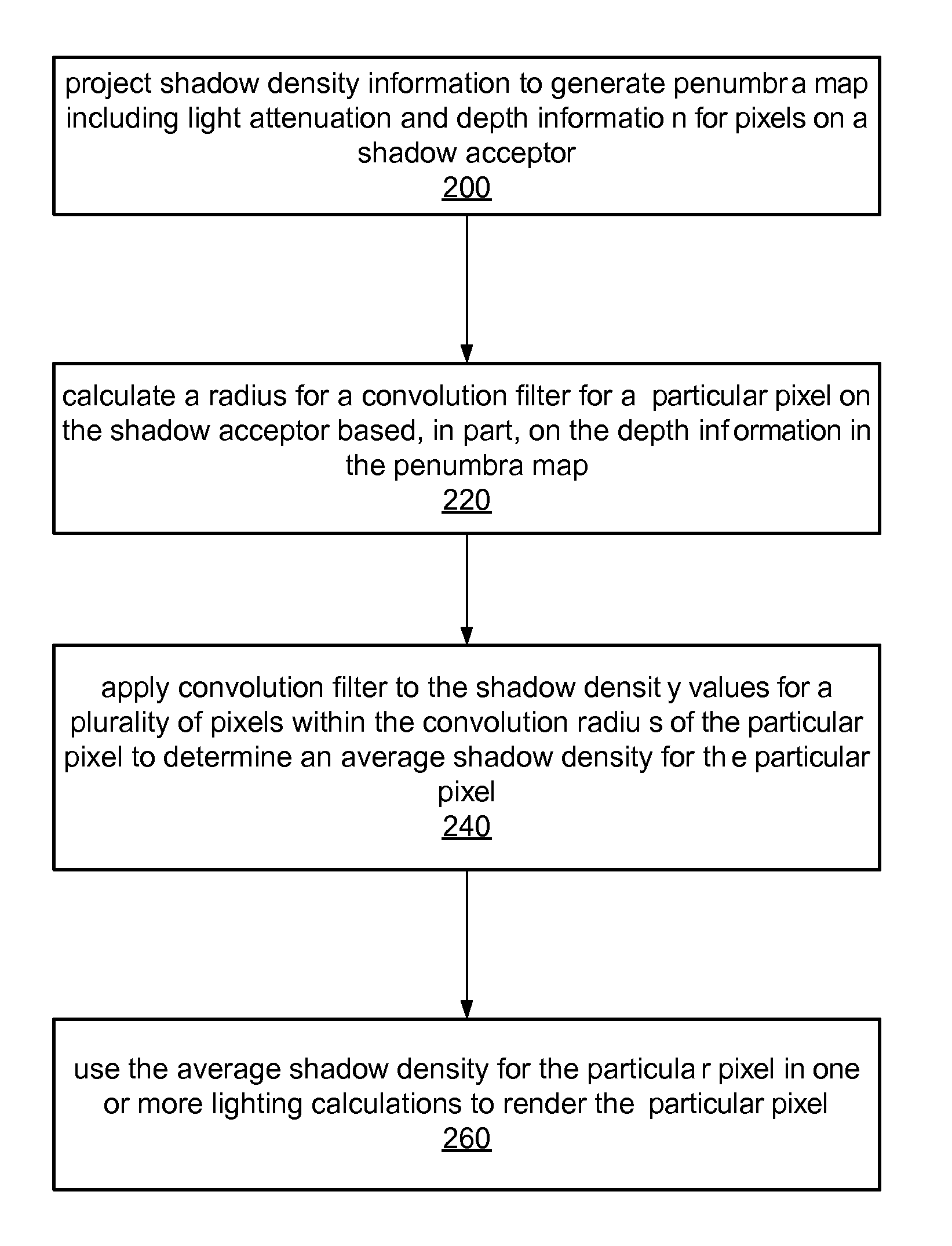
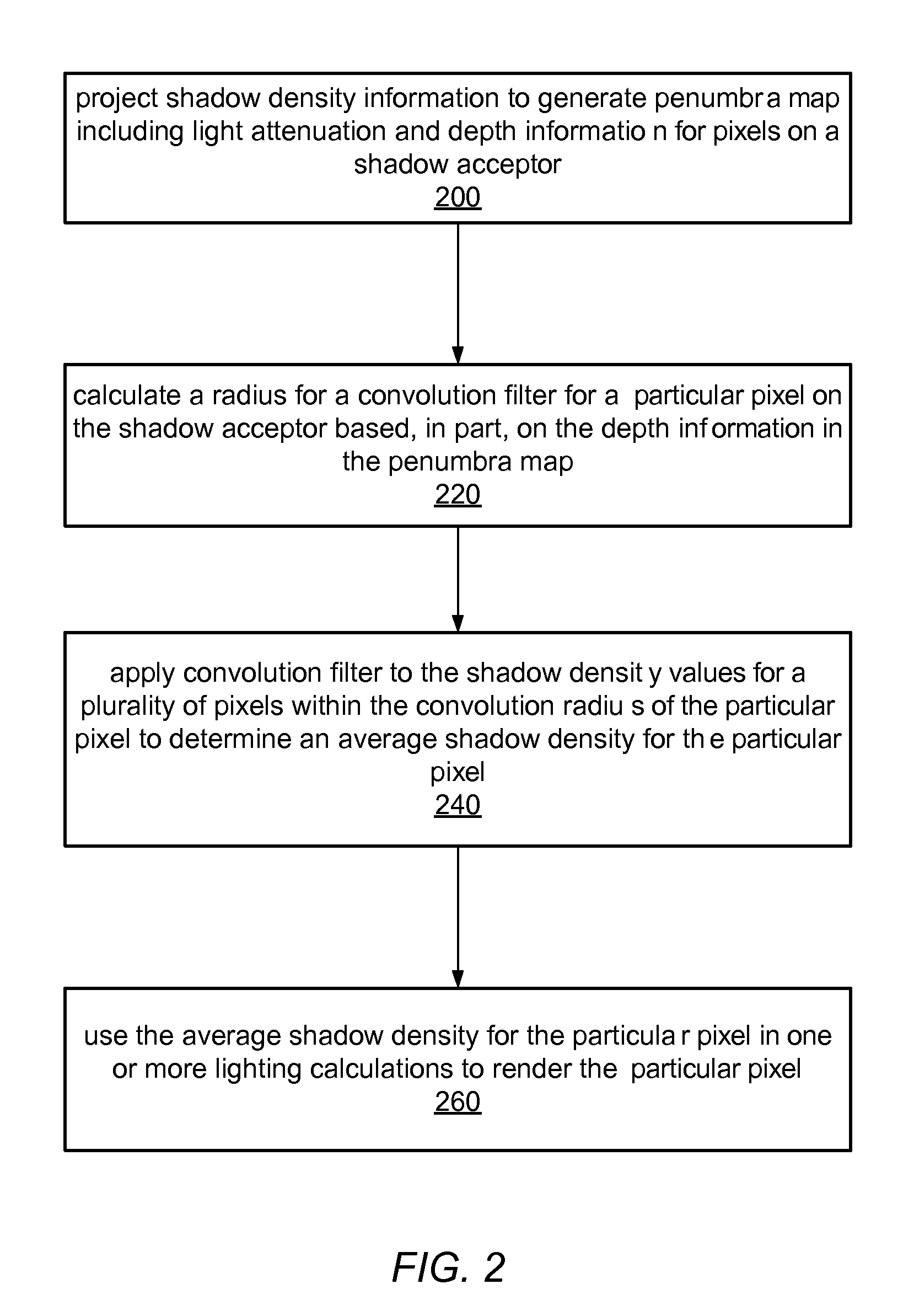
[0021]As noted above, shadows from genuine, physical lights have a penumbra region, in which the light is only partially hidden from the shadow acceptor. The intensity of this region may be calculated using an approximation of the amount of light source visible. While the techniques described herein may be used with area lights of any, arbitrary shape generally, for ease of discussion, the examples and exemplary embodiments described and illustrated include spherically shaped light sources. As will be described in more detail below, calculating the intensity of a penumbra region may be performed on a graphics processing unit (GPU), such as by using projected intensities from a shadow-attenuation, or shadow density, map. Thus, a shadow, as projected from a area light source, may be calculated on a GPU using fragment, or pixel, shader programs that calculate the light intensities for each pixel being rendered.

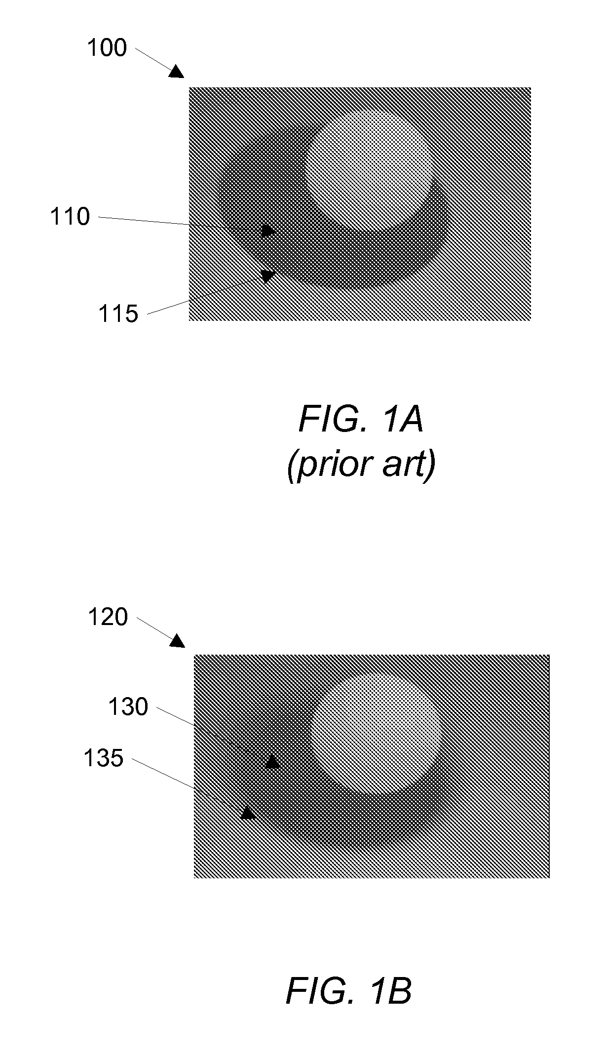
[0022]FIG. 1A illustrates an image 100 that includes a shadow 110 generated ...


PUM


Abstract

Shadows from physical lights have a penumbra region, in which the light is only partially hidden from the shadow acceptor. The intensity of light in this region may be calculated using an approximation of the amount of light visible. For example a fragment or pixel shader program execution on a GPU may generate a shadow from a light source using the light intensities for each pixel being rendered. Per-pixel shadow density information may be projected from the shadow caster onto the shadow acceptor. A penumbra map may contain both depth information and light attenuation information for the shadow acceptor. This information may be blurred using a fragment or pixel shader on a GPU to determine an average shadow density for a pixel being rendered.

Description

BACKGROUND[0001]1. Field of the Invention[0002]The present invention is directed to computer systems. More particularly, it is directed to graphical image processing including the generation of shadows with penumbra.[0003]2. Description of the Related Art[0004]Light emanating from a point will not have a penumbra as the shadow acceptor will either receive no light or full light. Penumbrae from area light sources are done on the CPU by either stochastic ray casting or by other generally execution-expensive geometrical projections. Shadows from such point light sources have been calculated on the GPU from some time using various types of shadow maps that generally include only depth information, such as indicating a distance between a light source and a shadow caster. Such techniques may not well-suited for calculating light from area light sources.SUMMARY[0005]Shadows from physical lights have a penumbra region, in which the light is only partially hidden from the shadow acceptor. Th...

Claims


Application Information

Patent Timeline
IPC IPC(8): G06K9/00G06T15/50
CPCG06T15/60
Inventor O'DONNELL, DANIEL
Owner ADOBE INC
Why Eureka
Try Eureka