Rotary valve

a technology of rotary valves and valve bodies, applied in the direction of valve operating means/release devices, water supply installation, separation processes, etc., can solve the problems of changing the shape of the surface, allowing leakage across the seal formed between the surface and various operating problems, etc., to reduce the amount of torque

Active Publication Date: 2010-10-26
AIR PROD & CHEM INC
View PDF23 Cites 71 Cited by
  • Summary
  • Abstract
  • Description
  • Claims
  • Application Information

AI Technical Summary

Benefits of technology

[0023]A rotary valve having a rotor and a stator in a sealed sliding rotary motion is disclosed. The rotary valve includes compression springs configured to reduce the amount of torque required to rotate the rotors while preventing leakage. The valve may be used in a cyclic processes including a PSA process for directing fluids from one or more process sources to one or more process destinations in repeatable cyclic process steps.
[0027]Another embodiment of the invention is disclosed that provides for a rotary valve for performing cyclic process operations including a stator housing having ports, a rotor comprising ports and a rear surface, the rotor in rotatable contact about a center axis of rotation with the stator housing at an interface, at least one compression spring having a spring force center of force disposed between the rotor rear surface and a thrust runner; and a thrust bearing disposed between the thrust runner and the stator housing. The rotary valve further includes having the at least one compression spring apply a spring force configured to minimize torque required to turn the rotor for the given spring force when the valve is operational.
[0028]The rotary valve further includes having the spring force center of force located at a predetermined distance greater than zero from the axis of rotation, and having at least one spring locating feature on the rotor rear surface to position the at least one compression spring. The rotary valve may further include having two or more spring locating features on the rotor rear surface opposite two or more spring locating features located similarly on the thrust runner to secure and position two or more compression springs between the feed rotor and the thrust runner at a fixed position.
[0030]The rotary valve includes one or more rotors configured to rotate about an axis of rotation; and at least one compression spring having a spring force with a center of force configured to apply the spring force to the one or more rotors that minimizes the torque required to turn the one or more rotors for the spring force applied.

Problems solved by technology

Rigid materials such as metals, ceramics, and / or carbon are typically are used for these rotors and stators, but wear of the parts or distortions caused by temperature differentials may cause changes in the shape of the surfaces, thereby allowing leakage across the seal formed between the surfaces.
When the PSA cycle includes process steps at positive pressure and under vacuum, leakage driven by the pressure differentials between the valve ports connected to the feed and product ends of the beds may lead to various operating problems if leaks occur between these ports.
During operation of the prior art rotary valve disclosed in the '859 application, the difference in the port pressures results in a non-axial force across the rotor and stator mating face.
When high operating pressures are required, large spring forces may be required to seal the rotors against the stators and prevent leakage.
If high spring forces are required to prevent leakage between the rotor and stator, large forces will be required to turn the rotors.
These large forces increase rotor wear, require larger rotor motors, and increase rotor bearing wear.
For larger rotors, this may become impractical.
Even in applications when the bending moment and deflection are not of significant concern, the torque required to turn the motor and rotate the rotors may be a significant concern, especially when high pressures are present in the rotor ports.

Method used


Image

  • Rotary valve
  • Rotary valve
  • Rotary valve

Examples


Embodiment Construction

[0046]The present invention now will be described more fully hereinafter with reference to the accompanying drawing, in which a preferred embodiment of the invention is shown. This invention may, however, be embodied in many different forms and should not be construed as limited to the embodiments set forth herein; rather, these embodiments are provided so that this disclosure will be thorough and complete and will fully convey the scope of the invention to those skilled in the art.

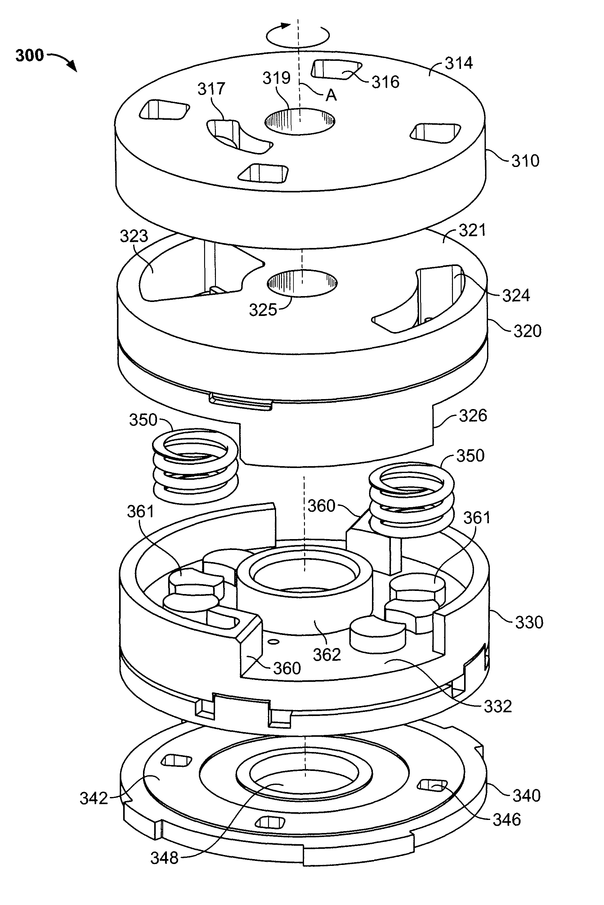
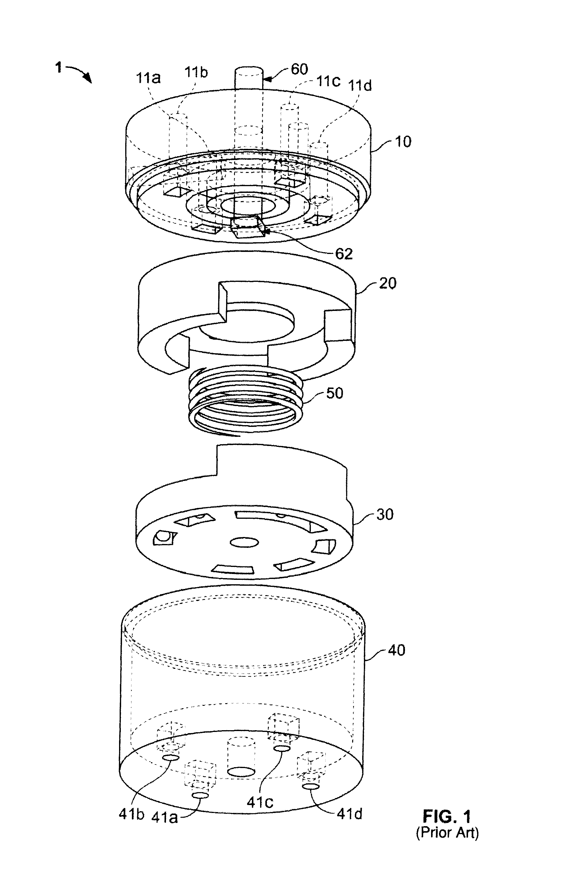
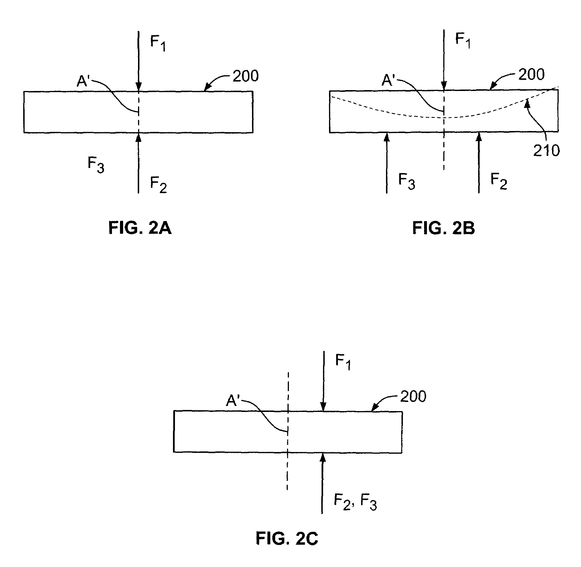
[0047]The exemplary embodiments of the present invention address the operation of a rotary valve that may be utilized in a pressure swing absorption (PSA) system operating in cycles by rotating a rotor within the rotary valve. The PSA systems include PSA systems having pressures that are super-atmospheric or sub-atmospheric or a combination of super- and sub-atmospheric. The exemplary embodiments of the invention provide for an improved rotary valve design and method of configuring a rotary valve that red...


PUM


Abstract

A rotary valve is disclosed having a rotor and stator that utilizes at least one compression spring to provide contact between the rotor and stator. The spring(s) is configured to oppose the pressure forces that urge the rotors and stators apart and reduce the amount of torque necessary to turn the rotors in the valve while preventing leakage from between the rotor and stator. The spring(s) may be positioned within the valve by a spring locating features.

Description

BACKGROUND OF THE INVENTION[0001]This invention relates generally to a rotary valve, and more particularly, to a rotary valve for pressure swing absorption systems.[0002]Rotary valves are widely used in the process industries for directing fluids from one or more process sources to one or more process destinations in repeatable cyclic process steps. These valves, also called rotary sequencing valves, are used in cyclic or repeatable processes, such as gas separation by pressure or temperature swing adsorption, liquid separation by concentration swing adsorption, gas or liquid chromatography, regenerative catalytic processes, pneumatic or hydraulic sequential control systems, and other cyclic processes.[0003]A widely used type of rotary valve has a planar circular configuration in which a flat, ported rotor rotates coaxially on a flat, ported stator such that ports in the stator and rotor are either aligned or blocked in a predetermined cyclic sequence. Sealing typically is provided ...

Claims


Application Information

Patent Timeline
Patent Type & Authority Patents(United States)
IPC IPC(8): B01D59/26
CPCF16K11/074F16K3/10C01B13/0259B01D53/047B01D2259/40005Y10T137/88102Y02P20/141F16K3/24F16K3/314
Inventor WAGNER, GLENN PAUL
Owner AIR PROD & CHEM INC
Why Eureka
Try Eureka