Image pickup system

a pickup system and image technology, applied in the field of image pickup systems, can solve the problem that ccd cannot be used in some cases

Inactive Publication Date: 2010-10-26
OLYMPUS CORP
View PDF21 Cites 55 Cited by
  • Summary
  • Abstract
  • Description
  • Claims
  • Application Information

AI Technical Summary

Benefits of technology

[0031]a video signal processing circuit provided in the camera control unit for performing video-signal proces...

Problems solved by technology

Thus, there is a problem that su...

Method used


Image

  • Image pickup system
  • Image pickup system
  • Image pickup system

Examples


first embodiment

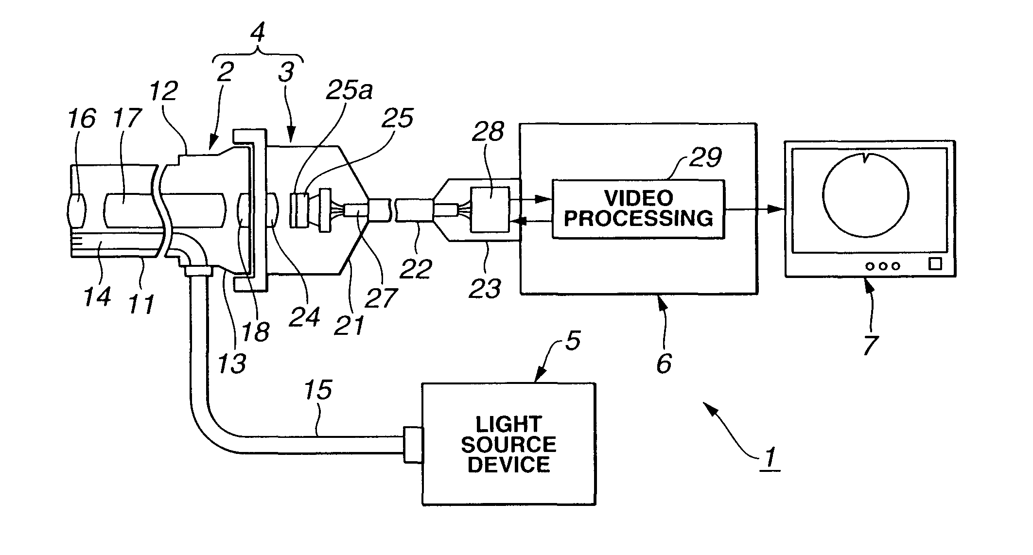
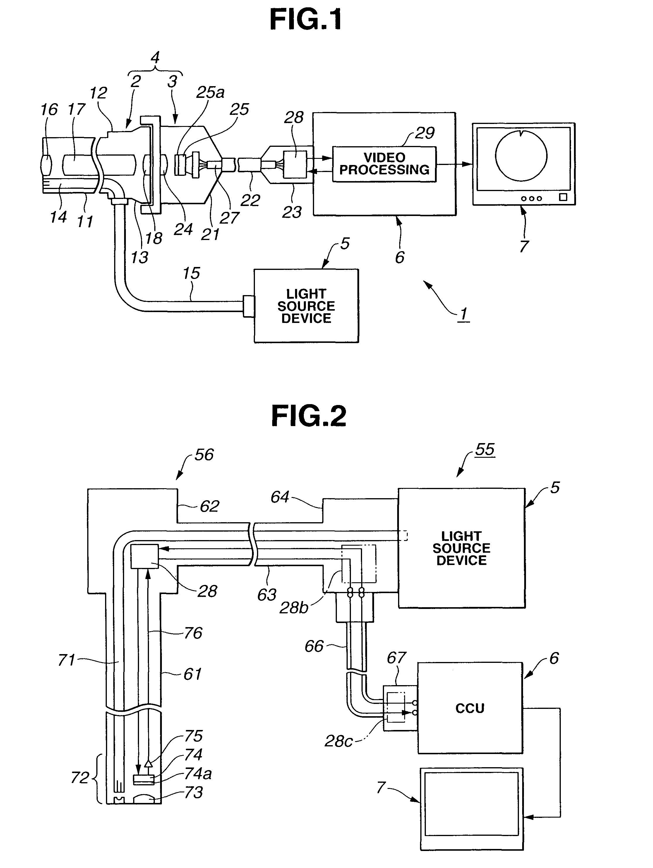
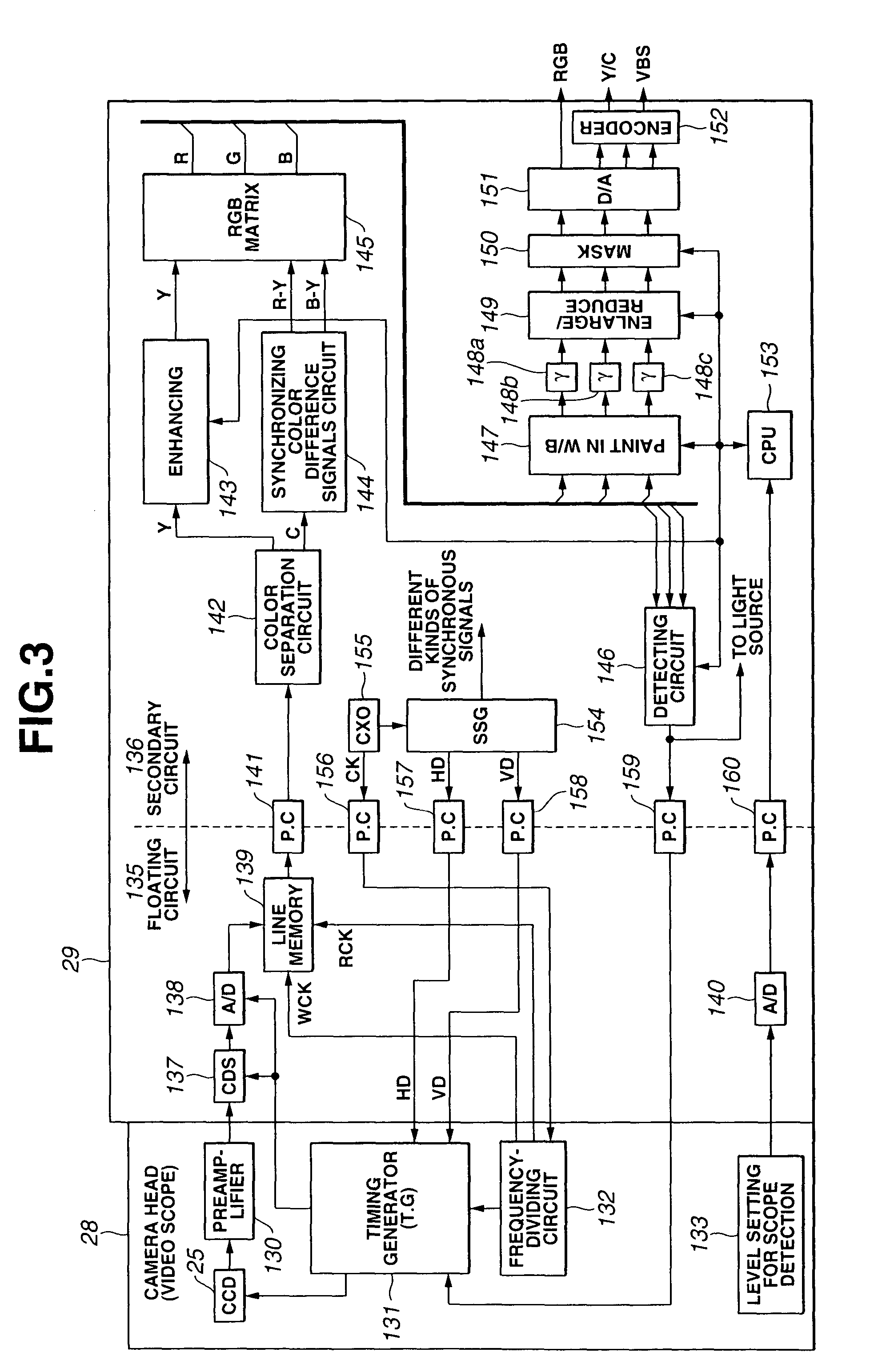
[0047]FIGS. 1 to 10 relate to a first embodiment of the present invention. FIG. 1 is a configuration diagram showing a configuration of an endoscope apparatus; FIG. 2 is a configuration diagram showing a configuration of a modification example of the endoscope apparatus in FIG. 1; FIG. 3 is a block diagram showing a configuration of an upstream processing circuit and a video processing circuit; FIG. 4A to FIG. 4D are a first diagram for explaining operations of the upstream processing circuit and the video processing circuit in FIG. 3; FIG. 5 is a second diagram for explaining operations of the upstream processing circuit and the video processing circuit in FIG. 3; FIG. 6 is a third diagram for explaining operations of the upstream processing circuit and the video processing circuit in FIG. 3; FIG. 7 is a fourth diagram for explaining operations of upstream processing circuit and the video processing circuit in FIG. 3; FIG. 8A and FIG. 8B are a fifth diagram for explaining operation...

second embodiment

[0096]FIGS. 11 to 14 relate to a second embodiment of the present invention. FIG. 11 is a block diagram of a configuration of the upstream processing circuit and the video processing circuit according to the second embodiment of the present invention; FIG. 12A to FIG. 12D are a first diagram for explaining operations of the upstream processing circuit and the video processing circuit in FIG. 11; FIG. 13A to FIG. 13C are a second diagram for explaining operations of the upstream processing circuit and the video processing circuit in FIG. 11; and FIG. 14 is a third diagram for explaining operations of the upstream processing circuit and the video processing circuit in FIG. 11.

[0097]The second embodiment is mostly the same as the first embodiment. Thus, only different points will be described. The same reference numerals are given to the same components, and the description will be omitted.

[Configuration]

[0098]This embodiment has a terminal for inputting video signal from the outside. ...


PUM


Abstract

To provide an image pickup system having CCDs 25 driven at different frequencies respectively which can drive each CCD 25 with a predetermined frequency if a detachable camera head (or electronic endoscope) 28 is used and also can process a signal processing clock of a video processing circuit 29 with one type of clock. A drive signal of the predetermined frequency supplied to the CCD is produced via a generating circuit CXO 155 in the video processing circuit 29, a frequency dividing circuit 132 and a timing generator (T.G.) 131. A CCD signal outputted from the CCD 25 is inputted to a line memory 139 in a floating circuit 135. As a writing clock (WCK) of the line memory 139, the one which is divided in the frequency dividing circuit 132 to a frequency in accordance with the CCD 25 to be used is used, and as a reading clock (RCK), the one of one type of frequency is used without regard to the CCD 25 to be used. Hence, it is possible to perform the signal processing of a secondary circuit 136 of the line memory 139 and following ones always with a common generating clock.

Description

CROSS REFERENCE TO RELATED APPLICATION[0001]This application is a continuation application of PCT / JP02 / 02400 filed on Mar. 14, 2002 the disclosure of which is incorporated herein by its reference.TECHNICAL FIELD[0002]The present invention relates to an image pickup system having a feature in a control portion for a drive signal and an image pickup signal of a solid image pickup element such as CCD.BACKGROUND ART[0003]Recently, endoscope apparatus have been widely spread for performing observation and processing on an observed part by inserting an inserting portion to the observing part within a body cavity, for example, and by transmitting illumination light from an illumination light transmitting unit, such as a light guide fiber flux and irradiating it to the observing part from the distal end of the inserting portion so as to obtain an image of the observed part.[0004]One of the endoscope apparatus is an electronic endoscope apparatus, which is provided with a solid image pickup ...

Claims


Application Information

Patent Timeline
IPC IPC(8): A62B1/04A61B1/04G02B23/24A61B1/05H04N5/225H04N5/232H04N7/18
CPCH04N5/335A61B1/05H04N2005/2255H04N23/555H04N25/00
Inventor MOCHIDA, AKIHIKOSAITO, KATSUYUKITSUNAKAWA, MAKOTOKUSAMURA, NOBORUOGASAWARA, KOTAROTASHIRO, HIDEKI
Owner OLYMPUS CORP
Why Eureka
Try Eureka