Receiving apparatus and method thereof

a technology for receiving apparatus and data signals, applied in the direction of pulse technique, amplitude demodulation, line-faulst/interference reduction, etc., can solve the problem that the above-described conventional process may typically not be employed, and achieve the effect of reducing chip area and power consumption

Active Publication Date: 2010-10-26
SAMSUNG ELECTRONICS CO LTD
View PDF10 Cites 28 Cited by
  • Summary
  • Abstract
  • Description
  • Claims
  • Application Information

AI Technical Summary

Benefits of technology

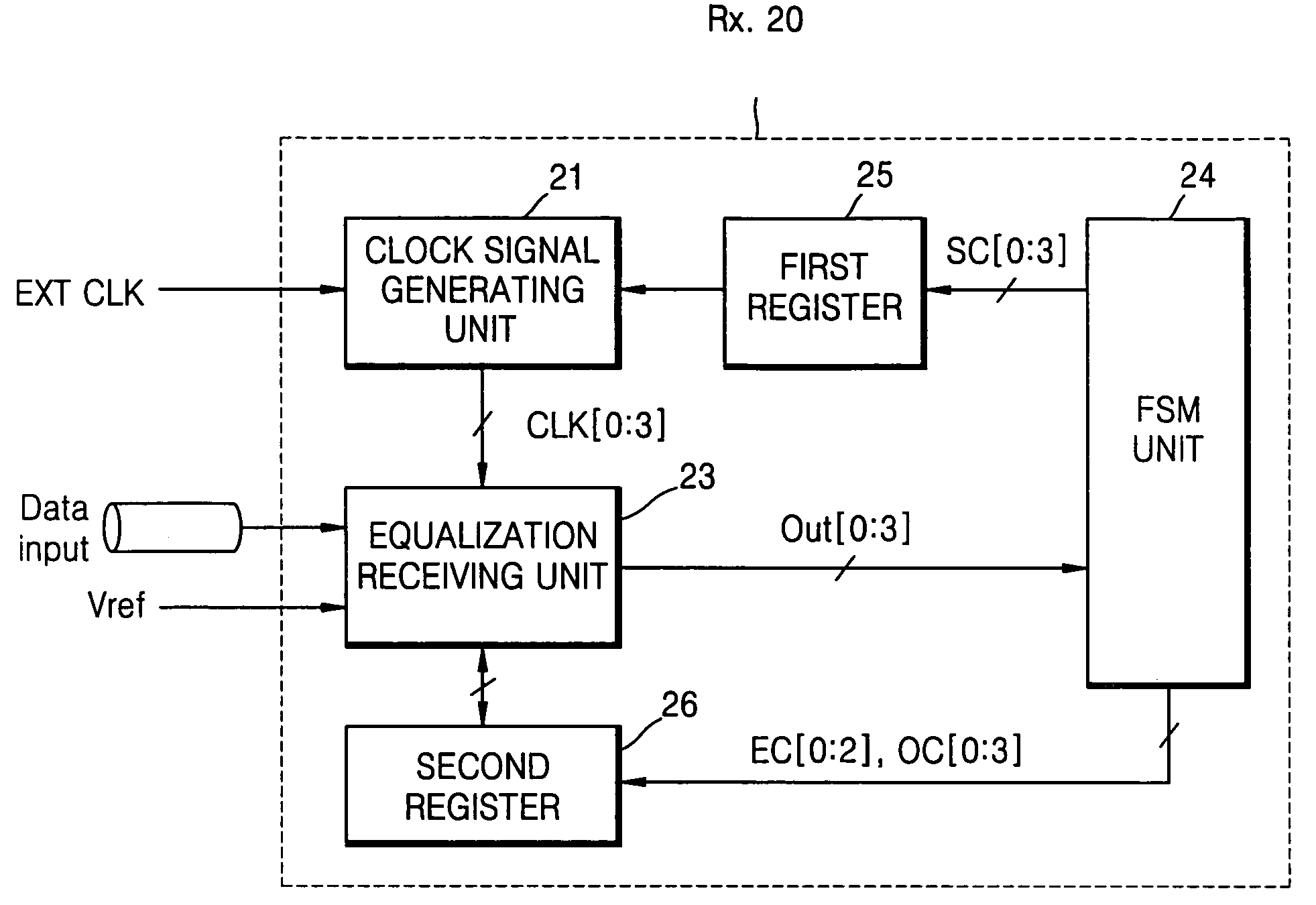
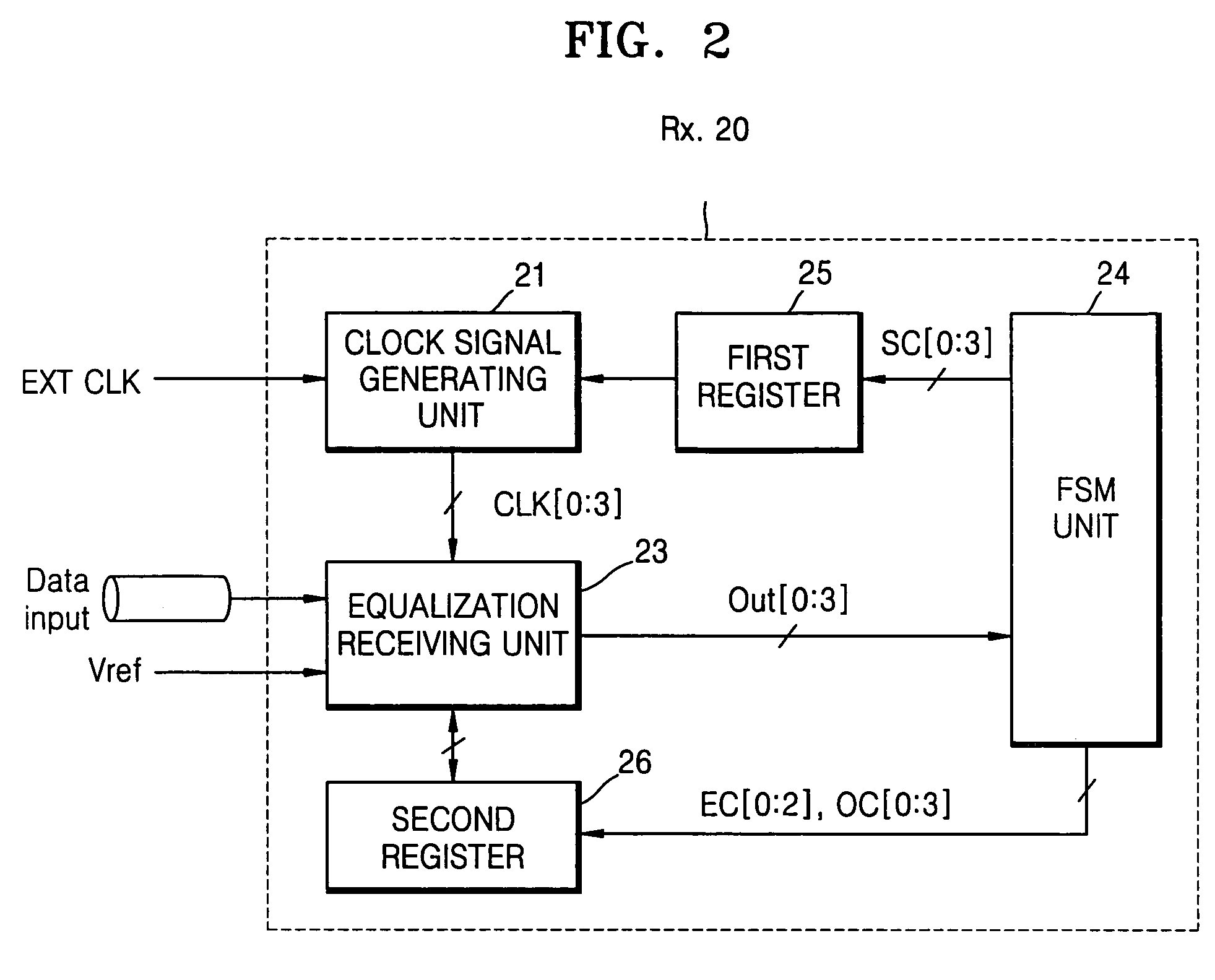
[0010]Another example embodiment of the present invention is directed to a receiving apparatus which may be applied to a DRAM interface system and may perform digital compensation with reduced power consumption and / or reduced chip area.

Problems solved by technology

However, in a number of conventional memory types (e.g., a dynamic random access memory (DRAM)), the above-described conventional process may typically not be employed due to performance degrading characteristics such as an increased latency, an increased chip area and / or an increased power consumption.

Method used


Image

  • Receiving apparatus and method thereof
  • Receiving apparatus and method thereof
  • Receiving apparatus and method thereof

Examples


Embodiment Construction

[0021]Detailed illustrative example embodiments of the present invention are disclosed herein. However, specific structural and functional details disclosed herein are merely representative for purposes of describing example embodiments of the present invention. Example embodiments of the present invention may, however, be embodied in many alternate forms and should not be construed as limited to the embodiments set forth herein.

[0022]Accordingly, while example embodiments of the invention are susceptible to various modifications and alternative forms, specific embodiments thereof are shown by way of example in the drawings and will herein be described in detail. It should be understood, however, that there is no intent to limit example embodiments of the invention to the particular forms disclosed, but conversely, example embodiments of the invention are to cover all modifications, equivalents, and alternatives falling within the spirit and scope of the invention. Like numbers may ...


PUM


Abstract

Example embodiments relate to a receiving apparatus and method thereof. In an example, the receiving apparatus may include a clock generating unit generating a plurality of internal clock signals based on a received external clock signal and an equalization receiving unit receiving the plurality of internal clock signals and an input signal. The equalization receiving unit may determine an offset value and an equalization coefficient in an initial setting mode and may adjust the received data signal based on the determined offset value and equalization coefficient.

Description

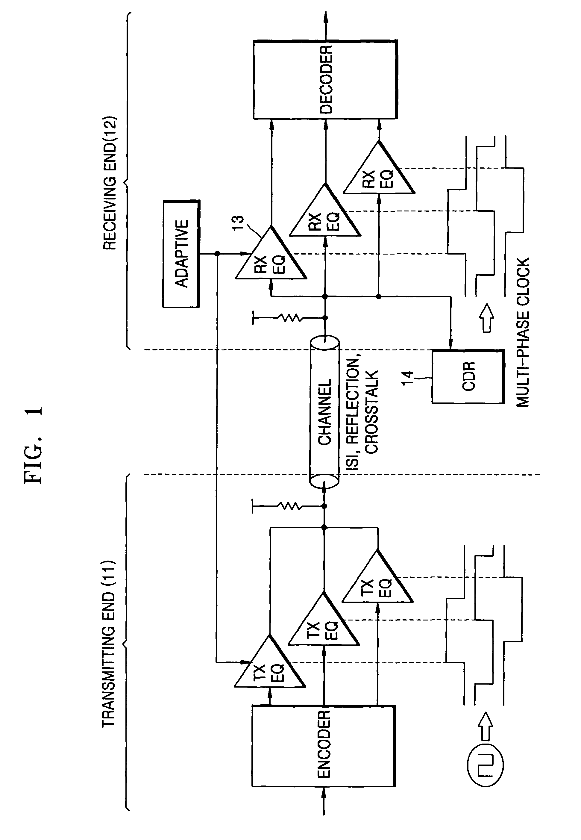
PRIORITY STATEMENT[0001]This application claims benefit of priority under 35 USC §119 from Korean Patent Application No. 10-2005-0011016, filed on Feb. 5, 2005, in the Korean Intellectual Property Office, the contents of which is incorporated herein by reference in its entirety.BACKGROUND OF THE INVENTION[0002]1. Field of the Invention[0003]Example embodiments of the present invention relate generally to a receiving apparatus and method thereof, and more particularly to a receiving apparatus for receiving a data signal and method thereof.[0004]2. Description of the Related Art[0005]FIG. 1 is a block diagram illustrating a conventional transceiver 100. Referring to FIG. 1, the transceiver 100 may include a transmitting end 11 and a receiving end 12. If the transmitting end 11 transmits data through a serial link (e.g., a universal serial bus (USB), an advance technology attachment (ATA), etc.), noise generated by inter-symbol interference (ISI), reflection and / or crosstalk of a chann...

Claims


Application Information

Patent Timeline
Patent Type & Authority Patents(United States)
IPC IPC(8): H03H7/30H03K5/159H03H7/40
CPCH04L7/0058H04L25/03038D05C9/06D05C17/00
Inventor SOHN, YOUNG-SOOBAE, SEUNG-JUNPARK, HONG-JUNCHOI, JUNG-HWAN
Owner SAMSUNG ELECTRONICS CO LTD
Why Eureka
Try Eureka