Enhanced object reconstruction

a reconstruction and object technology, applied in the field of image processing, can solve the problems of inability to effectively deal with the noise of sensors, the second method is typically computationally more expensive, and the sensor within the category is usually limited to sensing, so as to facilitate portability and use, and facilitate the efficient and accurate finding of the correspondence between the views.

Inactive Publication Date: 2010-10-26
QUALCOMM INC
View PDF34 Cites 31 Cited by
  • Summary
  • Abstract
  • Description
  • Claims
  • Application Information

AI Technical Summary

Benefits of technology

[0008]At least one disclosed implementation provides a three-dimensional digitizer system based on a stereovision passive sensing technique. Such a digitizer system is able to capture the scene in real time because it does not involve the physical movement of a component. The digitizer system also uses an infra-red filter to project a pattern onto the scene which enables the system to capture both the measurement image(s) and the texture image(s) simultaneously. These features make this system suitable not only for static objects, but also for three-dimensional reconstruction of dynamic scenes. The simple and straightforward principles of this system do not require complicated mechanical or electrical design or special installation. This system works in a normal office environment, requiring no controlled ambient lighting, and is therefore easy to port and to use. This system may also use a reference stripe as the pattern in stereovision, and may use a described matching propagation technique to assist in finding a correspondence between the views efficiently and accurately. The system also may perform filtering and smoothing using a Kalman filter and Non-Uniform Rational B-Spline surface fitting to attempt to effectively deal with the noise from sensors and numerical calculation.

Problems solved by technology

Sensors within this category are usually limited to sensing static scenes / objects because they usually need a certain amount of time to accomplish the scanning procedure due to the normal requirement of physically moving certain components in the scanning systems (e.g., components for emitting lasers within this category need to be moved to scan different lines of the object).
In addition, in situations in which the object of interest is a human being, illuminating patterns onto the face of the human being may cause discomfort to the eyes.
The area-based method (the second method), is typically computationally more expensive, but is typically able to generate dense matches.
The feature-based stereo matching method typically does not provide sufficient matched points for this purpose.
The area-based stereo matching method can typically generate sufficient numbers of three-dimensional samples on the surface, however, this method may have a long computation time, especially for high resolution capturing.

Method used


Image

  • Enhanced object reconstruction
  • Enhanced object reconstruction
  • Enhanced object reconstruction

Examples


Embodiment Construction

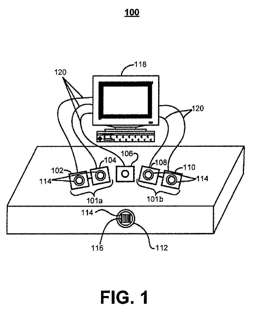
[0049]Referring to FIG. 1, an implementation for a three-dimensional digitizing system 100 is shown, which includes five cameras 102, 104, 106, 108, and 110. The cameras are arranged as two stereo pairs 101a and 101b, with stereo pair 101a including cameras 102 and 104, stereo pair 101b including cameras108 and 110, and as one texture camera 106. System 100 also includes a pattern projector 112, five infrared filters 114 (one on each of stereo cameras 102, 104, 108, and 110 and one on pattern projector 112), and a slide 116 having a pattern. As an illustrative example, slide 116 is shown with a vertical-line pattern. Cameras 102, 104, 106, 108, and 110 are coupled to a computer processor 118 via wires 120.

[0050]The three-dimensional digitizing system 100 is able to capture three-dimensional information of a dynamic or a static scene. System 100 uses infrared lighting to illuminate an object and uses infrared filters 114. System 100 illuminates the object with a desired pattern using...


PUM


Abstract

Processing images includes projecting an infra-red pattern onto a three-dimensional object and producing a first image, a second image, and a third image of the three-dimensional object while the pattern is projected on the three-dimensional object. The first image and the second image include the three-dimensional object and the pattern. The first image and the second image are produced by capturing at a first camera and a second camera, respectively, light filtered through an infra-red filter. The third image includes the three-dimensional object but not the pattern. Processing the images also includes establishing a first-pair correspondence between a portion of pixels in the first image and a portion of pixels in the second image. Processing the images further includes constructing, based on the first-pair correspondence and the third image, a two-dimensional image that depicts a three-dimensional construction of the three-dimensional object.

Description

CROSS-REFERENCE TO RELATED APPLICATION[0001]This application is a continuation application of U.S. patent application Ser. No. 11 / 327,651, filed Jan. 9, 2006, which claims the benefit of U.S. Provisional Application Ser. No. 60 / 641,752, filed Jan. 7, 2005, each of which is incorporated herein in its entirety for all purposes.TECHNICAL FIELD[0002]This disclosure relates to image processing.BACKGROUND[0003]Industrial products exist in the market for three-dimensional digitization for various purposes. Examples include medical applications, entertainment industry applications (e.g., three-dimensional gaming, filming, and animation), fashion design (e.g., three-dimensional garment design, apparel fitting, and plastic surgery), archaeological restoration and / or preservation, forensic applications (e.g., crime scene investigation), and online commodity exhibition (e.g., online museum and online store).[0004]There are, in general, two categories of three-dimensional digitizing techniques: ...

Claims


Application Information

Patent Timeline
Patent Type & Authority Patents(United States)
IPC IPC(8): G06K9/00H04N13/00G06T15/00G06V10/143G06V10/145
CPCG01B11/25G01B11/2545G06K9/2018G06K9/2036G06T7/0057G06T7/0065G06T2200/08G06T7/521G06T7/55G06V10/143G06V10/145H04N2013/0081G01B11/2513G06V2201/121
Inventor GU, JIN
Owner QUALCOMM INC
Why Eureka
Try Eureka