System and method for attaching panels to enable removal from the inside of a structure

a technology of mounting system and panel, applied in the field of panels, can solve the problems of difficult pin extraction, and achieve the effect of quick and easy access and operation

Inactive Publication Date: 2010-11-02
PANELSCAPE
View PDF32 Cites 11 Cited by
  • Summary
  • Abstract
  • Description
  • Claims
  • Application Information

AI Technical Summary

Benefits of technology

[0030]With all embodiments, when the assemblies are completed, the handle may be secured to the inside face of the panel, using hook and loop fastener, adhesive tape, suction cups or other suitable, temporary method of attachment. This permits the window or door being protected to be freely operated, prevents the cable from entanglement and places the handle in an easily accessible position so that the release mechanism may be quickly and easily accessed and operated. Ideally, all embodiments, when marketed, should be supplied with operating directions and warnings, clearly printed on a tag attached to the handle or directly embossed into the handle itself.

Problems solved by technology

The wing nuts are then tightened with sufficient tension to hold the panel firmly in place, but not with so much tension as to make it difficult to extract the pins.

Method used


Image

  • System and method for attaching panels to enable removal from the inside of a structure
  • System and method for attaching panels to enable removal from the inside of a structure
  • System and method for attaching panels to enable removal from the inside of a structure

Examples


first embodiment

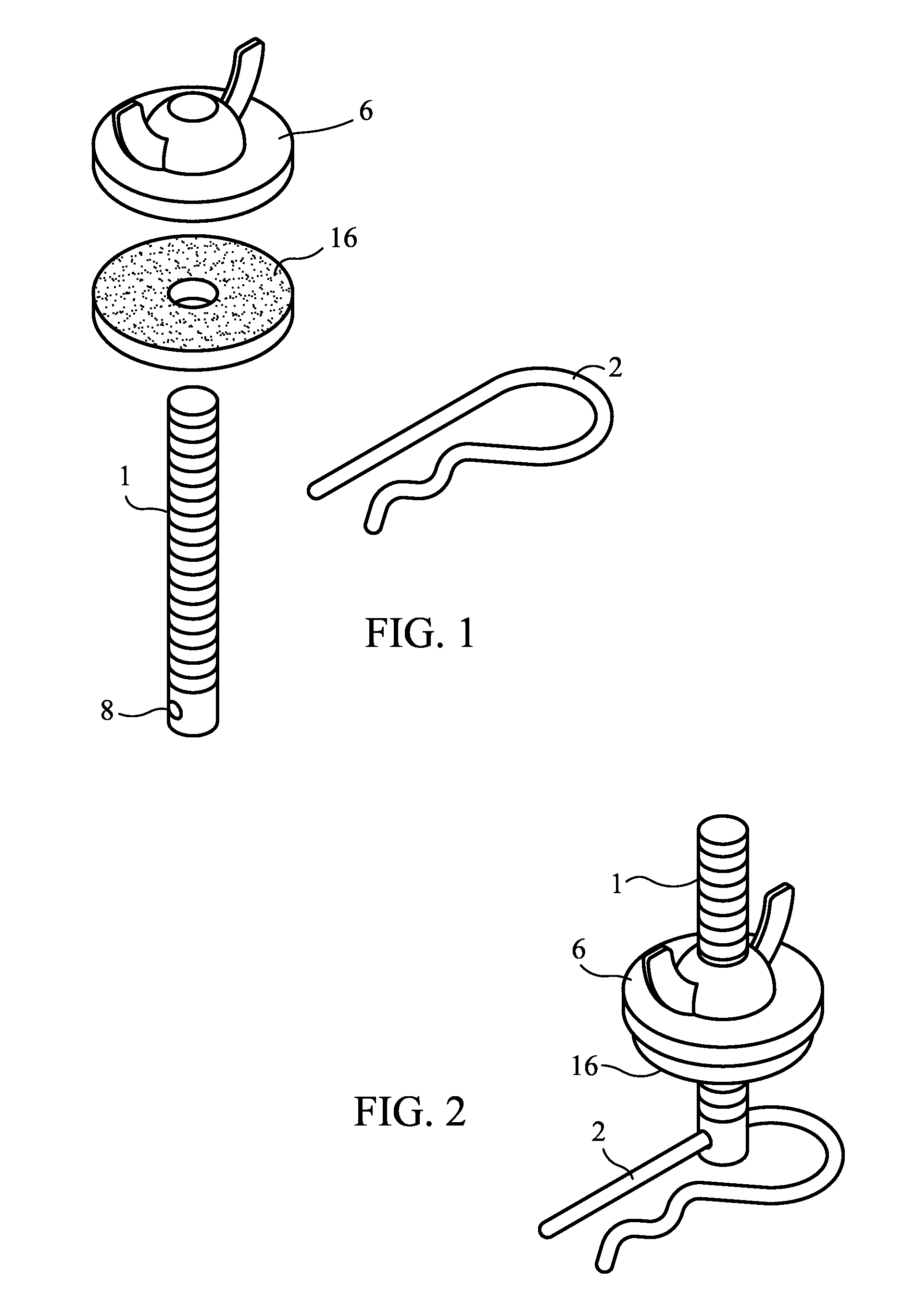
[0053]FIG. 1 shows the hardware components used with the first embodiment, which utilizes headless bolts 1, pins 2, neoprene washers 16 and wing nuts 6. The bolts 1 have holes 8 provided or drilled within close proximity to one end. The holes 8 are sufficiently large in diameter to accommodate the pin 2.

[0054]Hitch pin clips are preferably utilized for the pins 2, but any type of pin, for example a cotter pin or quick release pin, can be utilized, provided that the ring 3 can be attached to the pin 2, the pin 2 can pass through the hole 8 in the bolt 1, and the pin 2 can be removed from the bolt 1 by pulling on a handle (not shown), the object being to hold the bolts 1 in place and to facilitate extraction of the pins 2 and removal of the bolts 1 when desired. The pins 2 and bolts 1 are adapted to resist shear force deformation to enable disengagement of the pins 2 from the bolts 1. Likewise, the disengaging force is preferably aligned along an axis perpendicular to the axis of the ...

second embodiment

[0071]FIG. 10 shows the hardware components used with a second embodiment, which utilizes square headed bolts 20, pins 2, optional neoprene washers 16 and wing nuts 6. The bolts 20 have holes 8 provided or drilled within the square head. The holes 28 are sufficiently large in diameter to accommodate the pin 2. The square head of bolt 20 must not be larger than the opening on the front of the F-Track 13, and ideally the head should be sufficient in length and size to prevents the bolt 20 from rotating in the F track 13 thereby keeping the hole 8 aligned in place before the pin 2 is inserted. However, headless bolts with a hole in one end can also be utilized.

[0072]In this second embodiments, hitch pin clips are utilized for the pins 2, but any type of pin, for example a cotter pin or quick release pin can be utilized provided that the handle can be attached to the pin 2, the pin 2 can pass through the hole 28 in the bolt 20, and the pin 2 can be removed from the bolt 20 by pulling on...

third embodiment

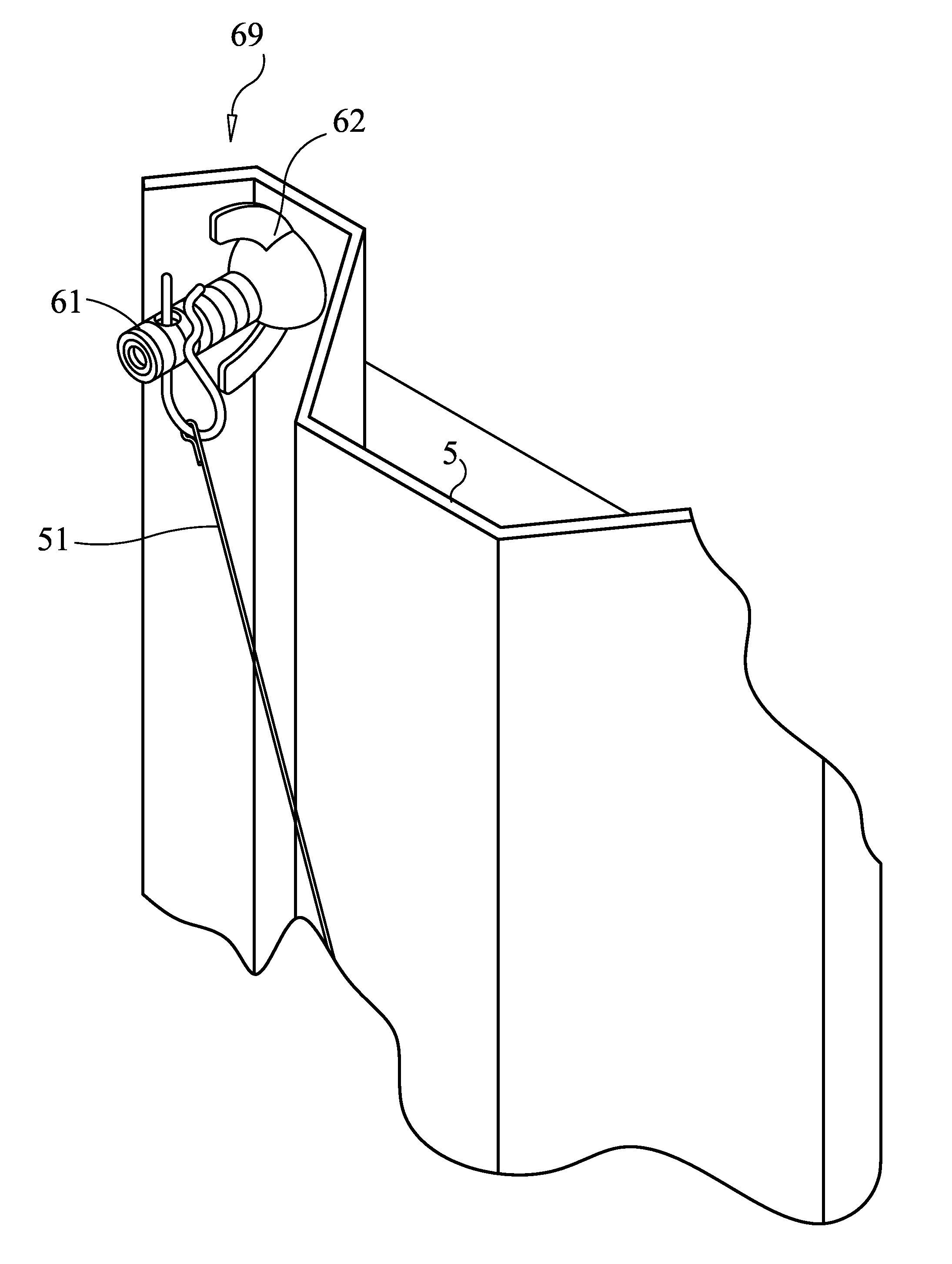
[0083]FIG. 17 shows an outside view of a panel 5 attached to a structure with the assembly 69 of this The pins 2 are located on the outside of the structure, and are attached to an alternate embodiment of the handle (not shown here and shown in FIG. 9A) by lines, wires or cables (also not shown). The handle is on the inside of the structure, and the lines, wires or cables 51 are passed through a hole (not shown) in the panel 5 located above and / or below the location of the pins 2. When the pins 2 are extracted by pulling on the handle, the sleeves 61 are released and the sleeves 61 and panel 5 come off the bolts 60 so the panel can be removed.

[0084]FIGS. 18 and 19 show an alternate implementation of the third embodiment. In this alternate implementation, sleeves 66 are of a slightly shorter length as the second end of the bolts 60, and are smooth on the inside with a diameter sufficient for the sleeves 66 to fit over the second end of the bolts 60. Specifically, the length of the s...


PUM


Abstract

A system and method which provides a means to install a hurricane shutter panel in a manner which enables release of the panel from the inside of the structure, thus providing means of egress through the opening on which the panel is installed. There are four preferred embodiments of the invention to correspond with the four primary means for installing hurricane shutter panels; namely angle track, F-Track, direct mount systems using wall anchors and direct mount systems using direct mount studs permanently mounted into a structure. The various embodiments require little or no modifications to the components of the various industry standard installation systems. The invention can be used with new installations or adapted to existing installations.

Description

FIELD OF THE INVENTION[0001]The invention relates to panels, particularly mounting systems and methods which permit removal of the hurricane panels from the inside of a structure. Hurricane panels are typically attached from the outside of a structure and are not removable from inside the structure. This system provides a means to release the panels from the inside of the structure, thus providing additional means of egress, should the primary means of egress become unusable.BACKGROUND OF THE INVENTION[0002]If a structure is to be occupied when hurricane panels are installed, it is necessary to have at least one opening where the hurricane protection system can be secured and removed from inside the structure. While other more expensive hurricane protection systems such as accordion shutters can be opened and closed from inside the structure, hurricane panels typically can only be attached or removed from outside of the structure.[0003]In recent years, many local governments in hurr...

Claims


Application Information

Patent Timeline
Patent Type & Authority Patents(United States)
IPC IPC(8): E04B2/82E06B3/26E05B65/10E06B3/68
CPCE06B9/02E06B2009/005F16B5/0208Y10T292/0822
Inventor VAN HORN STEEL, PHILIPLAGASSEY, PAUL J.
Owner PANELSCAPE
Why Eureka
Try Eureka