Stepper mechanism

a stepper mechanism and stepper technology, applied in the direction of article feeders, registering devices, article separation, etc., can solve problems such as distortion of printed images, and achieve the effect of reducing friction and reducing frictional resistan

Inactive Publication Date: 2010-11-02
OCE TECH
View PDF13 Cites 1 Cited by
  • Summary
  • Abstract
  • Description
  • Claims
  • Application Information

AI Technical Summary

Benefits of technology

[0009]It is an object of the present invention to provide a stepper mechanism with improved capabilities for correcting the position of the substrate, especially for substrates in sheet form.
[0012]Similarly, when the substrate is in the form of a web, e.g., a web that is drawn-off from a roll, the longitudinal direction of the web may deviate from the transport direction, due to tolerances in the suspension of the roll and / or in the feed mechanism with which the web is introduced into the stepper mechanism. Since the stepper mechanism feeds the web exactly in the transport direction, the left and right margins of the web in the portion on and directly upstream of the stepper mechanism will then be subject to different tensile forces, and if the web material has a certain elasticity, the web will be stretched on the side where the tensile forces are larger, and this may result in a distortion of the printed image. In the mechanism according to the present invention, the first transport member may be rotated such that the tensile forces in the web are balanced again when the web is gripped by the stationary member, so that no distortion of the web will occur on the stationary member and downstream thereof.
[0014]In a printer, the stepper mechanism may be provided on the upstream side or the downstream side of a print surface where the image is printed, e.g. by means of ink jet printheads arranged on a carriage that moves across the transport path. In order to permit full-bleed printing, a stepper mechanism according to the present invention may be provided on both, the upstream side and the downstream side of the print surface, or the print surface may be formed by the stationary member of the stepper mechanism. The stepper mechanism may also be integrated in the print surface. However, for certain types of printers, e.g., ink jet printers, it is advantageous that the print surface is perfectly flat. Then, it may be even more advantageous that the top surfaces of the stationary members and the transport members are exactly flush with each other, at least in the state in which the substrate is held at rest and the printhead is operating.
[0015]On the other hand, the stationary member and / or the transport members may be adapted to be lifted when they grip the substrate, and lowered when they release the same, in order to reduce the frictional resistance when the substrate is moved. As an alternative, friction may be reduced by creating an air cushion over which the substrate may slide. This option is particularly convenient in combination with a vacuum system for gripping the substrate by sucking the same against the stationary member and the transport members, respectively.
[0016]When the substrate takes the form of successive sheets, the stepper mechanism should be arranged such that the leading edge of each sheet can smoothly pass over the gap formed between the stationary member and each of the transport members. This can be achieved by forming the edges of the stationary member and the transport member facing each other as toothed edges which may mesh with each other, so that the leading edge of the sheet will be supported on the teeth of both members. Preferably, the teeth should have a tapered shape, such as for instance a triangular or trapezoidal shape, which provides a sufficient play for the rotation of the transport member relative to the stationary member even when the teeth of these members are meshing.

Problems solved by technology

Since the stepper mechanism feeds the web exactly in the transport direction, the left and right margins of the web in the portion on and directly upstream of the stepper mechanism will then be subject to different tensile forces, and if the web material has a certain elasticity, the web will be stretched on the side where the tensile forces are larger, and this may result in a distortion of the printed image.

Method used


Image

  • Stepper mechanism
  • Stepper mechanism
  • Stepper mechanism

Examples


Embodiment Construction

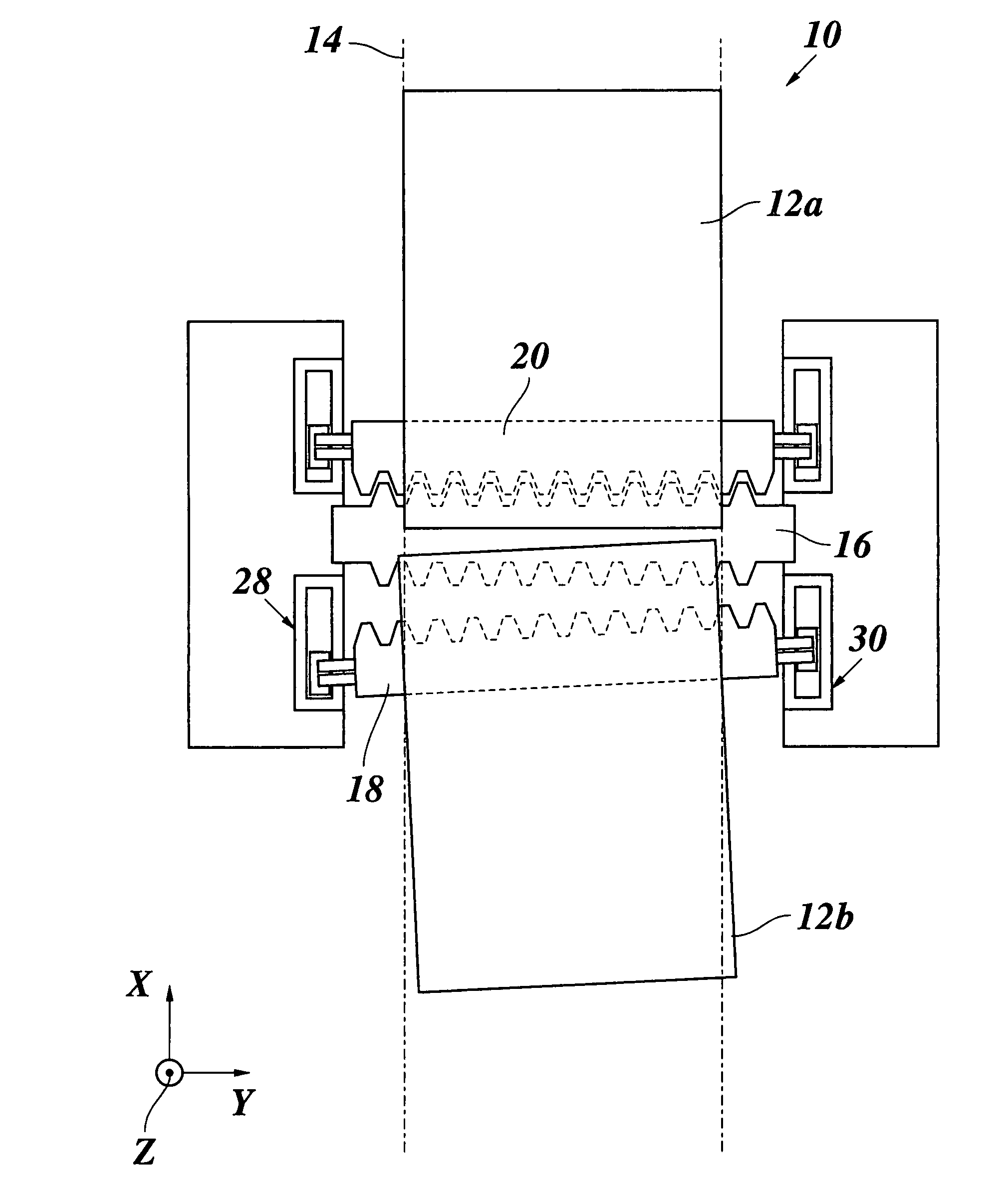
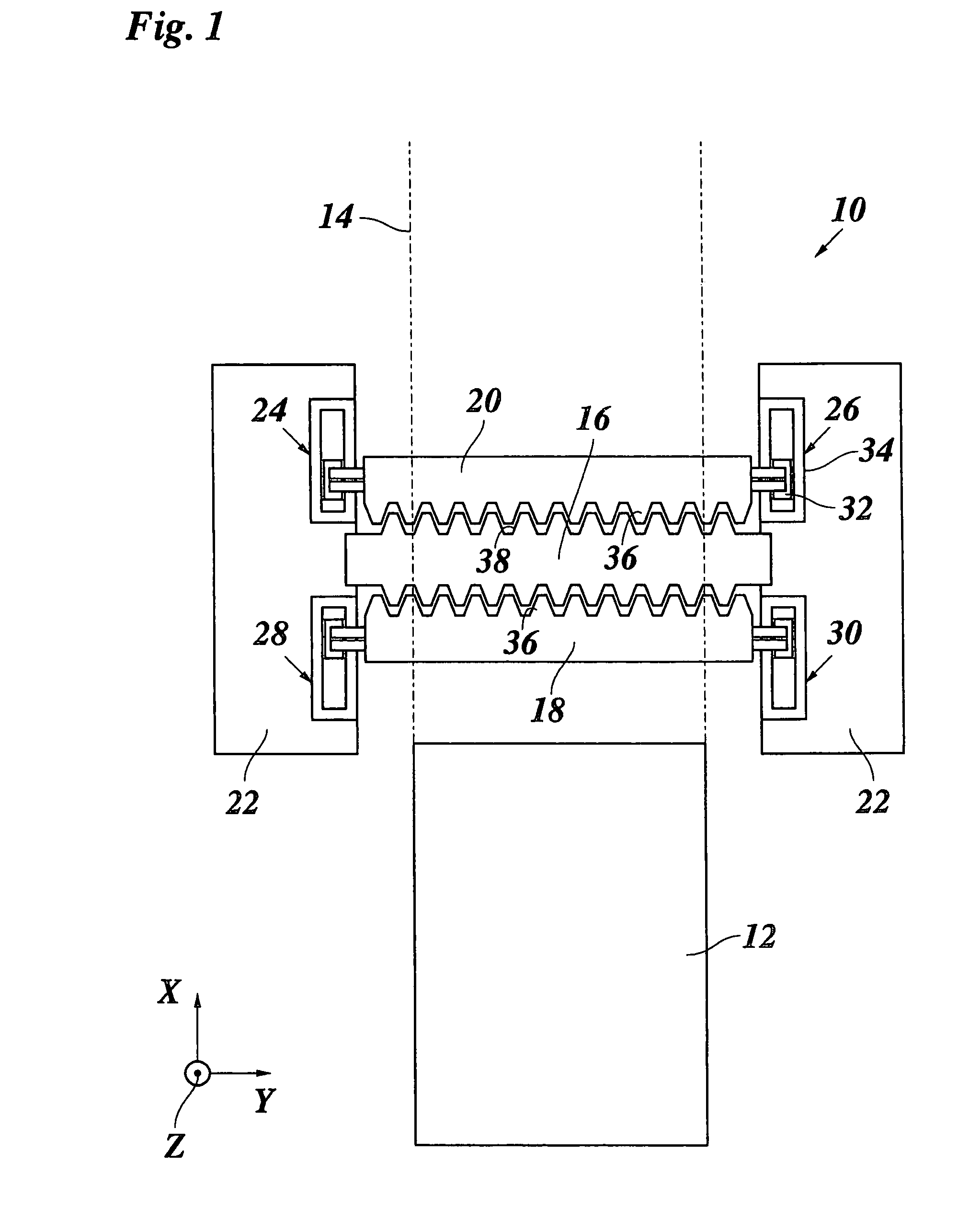
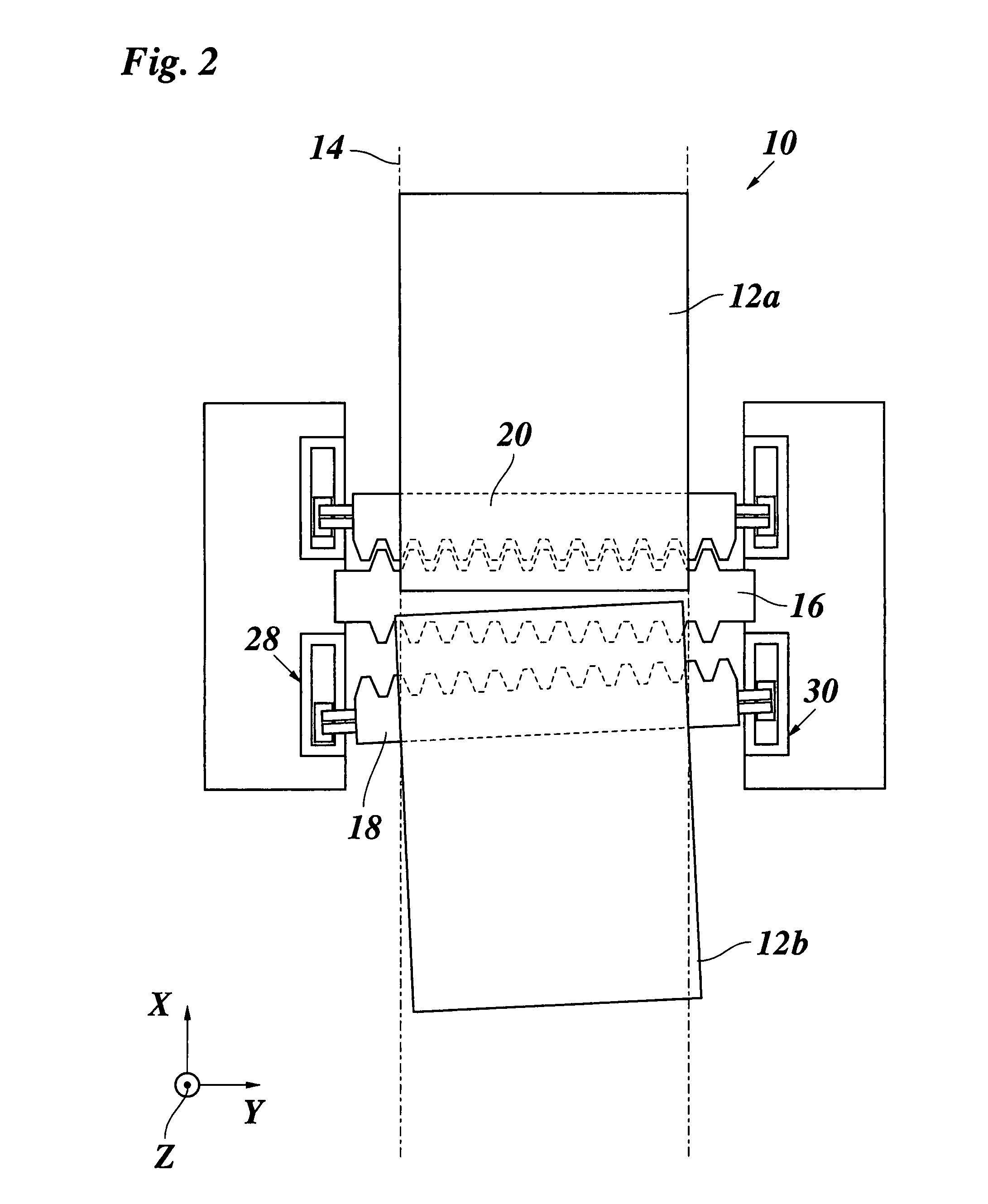
[0025]As is shown in FIG. 1, a stepper mechanism 10 is used for transporting a substrate 12, a sheet in this example, along a transport path 14. The transport mechanism 10 comprises a stationary member 16, a first transport member 18 and a second transport member 20. These members extend widthwise across the transport path 14. In the example shown, the stationary member 16 is arranged between the two transport members 18, 20.

[0026]The stationary member 16 is supported on frames 22 that are disposed on either side of the transport path 14.

[0027]The left and right ends of both transport members 18, 20 are supported on the frames 22 via separate drive units 24, 26, 28 and 30. In the example shown, each drive unit comprises a slide 32 which supports one end of the transport member and is guided and driven in a stator 34 which, together with the slide 32, forms a linear displacement system. Thus, each slide 32 is movable in a transport direction X in parallel with the transport path 14, ...


PUM


Abstract

A stepper mechanism for transporting a substrate along a linear transport path, which includes a stationary member and first and second transport members, extending widthwise across the transport path, the stationary member and transport members each being adapted to alternatively grip and release the substrate, and independent drive units are arranged on either side of the transport path for moving the respective ends of the transport members in a transport direction (X), wherein the transport members are movable independently of one another, and at least one of the drive units is adapted to move one end of the first transport member independently of the corresponding end of the second transport member.

Description

CROSS-REFERENCE TO RELATED APPLICATION[0001]This application claims priority from European Patent Application No. 06115164.3 filed on Jun. 8, 2006, the entire contents of which is hereby incorporated by reference in its entirety.BACKGROUND OF THE INVENTION[0002]1. Field of the Invention[0003]The present invention relates to a stepper mechanism for transporting a substrate along a linear transport path, comprising a stationary member and first and second transport members extending widthwise across the transport path, said stationary member and transport members each being adapted to alternatingly grip and release the substrate, and independent drive units arranged on either side of the transport path for moving the respective ends of the transport members in a transport direction.[0004]2. Description of Background Art[0005]A stepper mechanism of this kind may be used, for example, for transporting print substrates in the form of separate sheets or endless webs through a printer, e.g...

Claims


Application Information

Patent Timeline
Patent Type & Authority Patents(United States)
IPC IPC(8): B65H5/12
CPCB65H5/10B65H9/105
Inventor COENEN, JEROEN J. G.VAN DORP, BAE W. J. J. A.
Owner OCE TECH
Why Eureka
Try Eureka