Stator vane of turbo molecular pump

a technology of molecular pump and stator, which is applied in the direction of stators, machines/engines, liquid fuel engines, etc., can solve the problems of not being able to arrange them in the vacuum pump, and achieve the effect of reducing preventing the breakage of the stator van

Active Publication Date: 2010-11-02
EDWARDS JAPAN
View PDF7 Cites 12 Cited by
  • Summary
  • Abstract
  • Description
  • Claims
  • Application Information

AI Technical Summary

Benefits of technology

[0027]In the present invention, the construction that the gap is formed in the inner rim portion in the state that the two stator vane halves are abutted together. Thus, since occurrence of the overlap or warping in the inner rim portion can be prevented when the stator vane is arranged in the vacuum pump, breakage of the stator vane can be prevented, and the stator vane which can reduce breakage of the stator vane can be obtained.DETAILED DESCRIPTION OF THE PREFERRED EMBODIMENTS
[0037]This spacer 60 is constructed so that the upper and the lower spacers 60, 60 are fitted to each other in the state where the spacers 60 are stacked in stages in order to prevent lateral displacement of the spacer 60 in spacer stacking work in a pump assembling process and to enable positioning of the upper and the lower spacers 60, 60 in the cylindrical radial direction of the pump case 1 in the same way.
[0053]By this construction, when the two stator vane halves 30 are abutted to each other, a gap S is formed at the inner rim portion 32, which can prevent the above-mentioned overlap or warping at the inner rim portion 32 and reduce breakage of the stator vane B.

Problems solved by technology

Thus, it is not possible to arrange them in the vacuum pump by placing the center hole portions of the ring-shaped stator vanes B over the rotors.

Method used


Image

  • Stator vane of turbo molecular pump
  • Stator vane of turbo molecular pump
  • Stator vane of turbo molecular pump

Examples


Embodiment Construction

[0028]A best mode for carrying out the present invention will be described below in detail referring to the attached drawings.

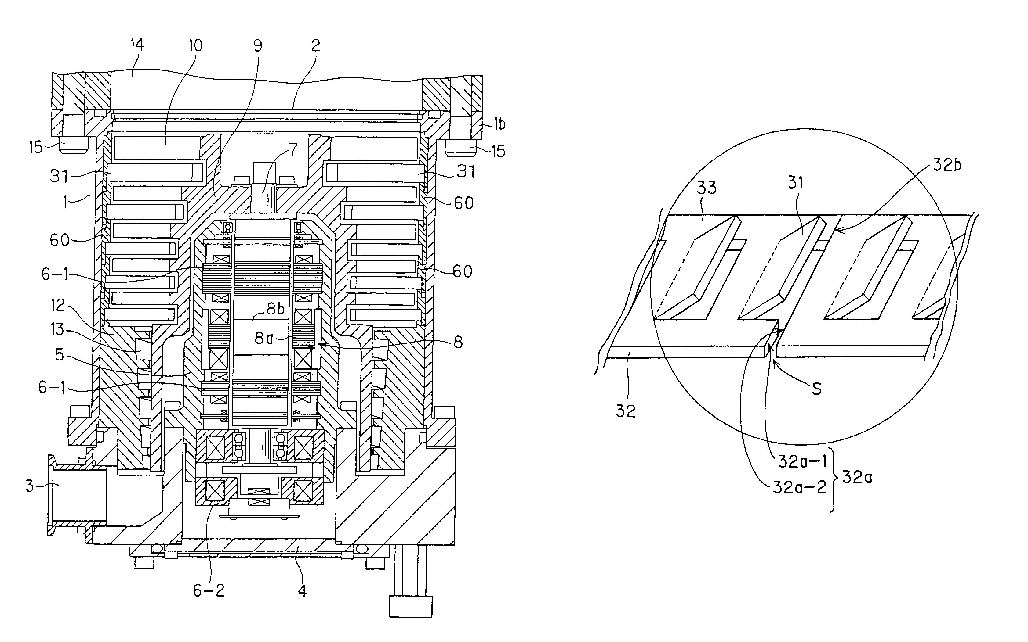
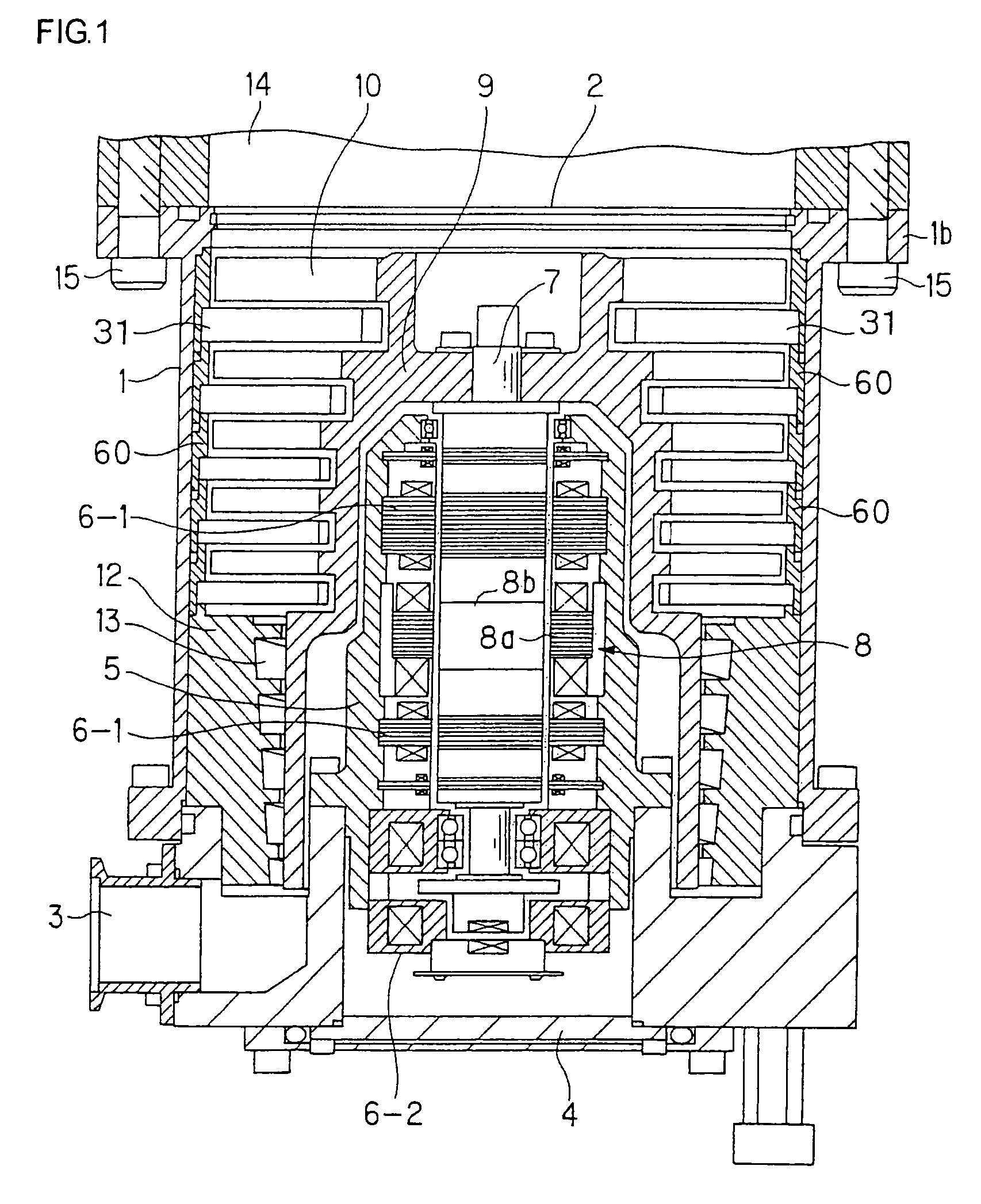
[0029]A vacuum pump shown in FIG. 1 is used as a part of a vacuum device in a semiconductor manufacturing apparatus or a liquid-crystal display panel manufacturing apparatus so as to bring a pressure in a vacuum chamber to a predetermined vacuum degree. Also, the vacuum pump in the same figure is a complex-type vacuum pump in which a turbo molecular pump and a screw groove pump are combined and constructed to have a rotor 9 rotatably arranged in a cylindrical pump case 1, in which a substantially upper half of the rotor 9 functions as a turbo molecular pump, while the substantially lower half of the rotor 9 functions as a screw groove pump.

[0030]This pump case 1 is in a cylindrical case structure with a bottom having an opening on its upper face as a gas inlet 2 and an exhaust pipe as a gas outlet 3 is projected on one side at the lower part. Also, the bottom...


PUM


Abstract

A stator vane for a turbo molecular pump has stator vane halves each having inner and outer rim portions and radially arranged stator blades connected integrally between the inner and outer rim portions. The inner rim portion of each stator vane half has a pair of inner rim ends and the outer rim portion of each stator vane half has a pair of outer rim ends. The stator vane halves are disposed in abutment with one another along an abutment line to form an annular body with the inner rim ends of one of the stator vane halves being disposed in confronting relation with the respective inner rim ends of the other of the stator vane halves and with the outer rim ends of the one of the stator vane halves being disposed in confronting relation with the respective outer rim ends of the other of the stator vane halves. At least each of the inner rim ends or each of the outer rim ends of one of the two stator blade halves being formed shorter in a circumferential direction of the annular body with respect to the abutment line to form a gap between the confronting inner rim ends or the confronting outer rim ends.

Description

CROSS-REFERENCE TO RELATED APPLICATIONS[0001]This application is a U.S. national stage application of International Application NO. PCT / JP2005 / 015518, filed Aug. 26, 2005, claiming a priority date of Sep. 10, 2004, and published in a non-English language.BACKGROUND OF THE INVENTION[0002]1. Technical Field[0003]The present invention relates to a stator vane of a turbo molecular pump and particularly to the reduction of breakage of the stator vane.[0004]2. Background Art[0005]A vacuum pump has, in general, a rotor rotatably installed inside a pump case and by high-speed rotation of this rotor, rotor vanes integrally cut out in a number of stages around the rotor are also rotated at a high speed. On the inner periphery of the pump case, stator vanes and the rotor vanes are alternately arranged in a number of stages.[0006]By interaction of the stator vanes and the rotor vanes arranged alternately in a number of stages, exhaust action of a gas molecule is carried out, and a process chamb...

Claims


Application Information

Patent Timeline
Patent Type & Authority Patents(United States)
IPC IPC(8): F01D9/04
CPCF04D19/042F04D29/542F04D19/04
Inventor AKIMOTO, TAKESHIKAWANISHI, SHINJI
Owner EDWARDS JAPAN
Why Eureka
Try Eureka