Resistor circuit and oscillation circuit

a resistor circuit and oscillation circuit technology, applied in the direction of resistor details, electric pulse generator circuits, instruments, etc., can solve the problem of deteriorating the resistance adjustment accuracy of the resistor circui

Inactive Publication Date: 2010-11-02
SEIKO EPSON CORP
View PDF5 Cites 8 Cited by
  • Summary
  • Abstract
  • Description
  • Claims
  • Application Information

AI Technical Summary

Problems solved by technology

When using a polysilicon wire as a wire provided across a guard ring formed to enclose the arrangement region of the fuse elements, the adjustment accuracy of the resistance of the resistor circuit deteriorates due to the parasitic resistance of the polysilicon wire.

Method used


Image

  • Resistor circuit and oscillation circuit
  • Resistor circuit and oscillation circuit
  • Resistor circuit and oscillation circuit

Examples


Embodiment Construction

[0037]Aspects of the invention may provide a resistor circuit which enables an accurate resistance adjustment and a reduction in circuit area, and an oscillation circuit including the same.

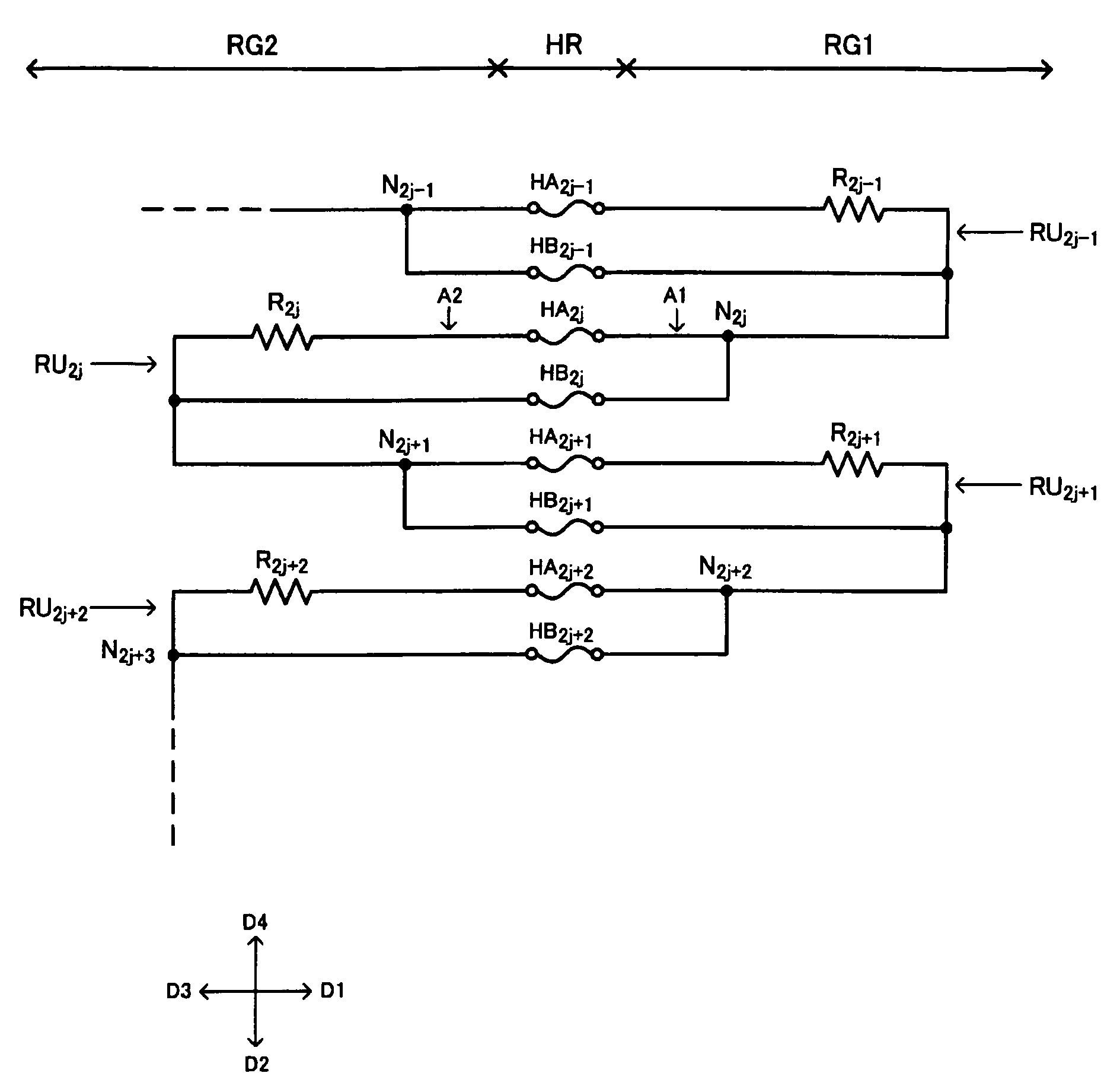
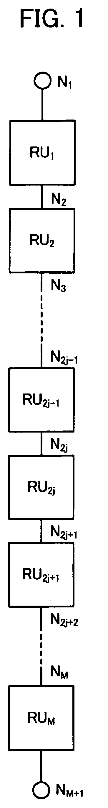
[0038]According to one embodiment of the invention, there is provided a resistor circuit comprising: first to Mth (M is an integer equal to or larger than two) resistor circuit units that are provided in series between a first node and an (M+1)th node,

[0039]a (2j−1)th (1≦2i−1

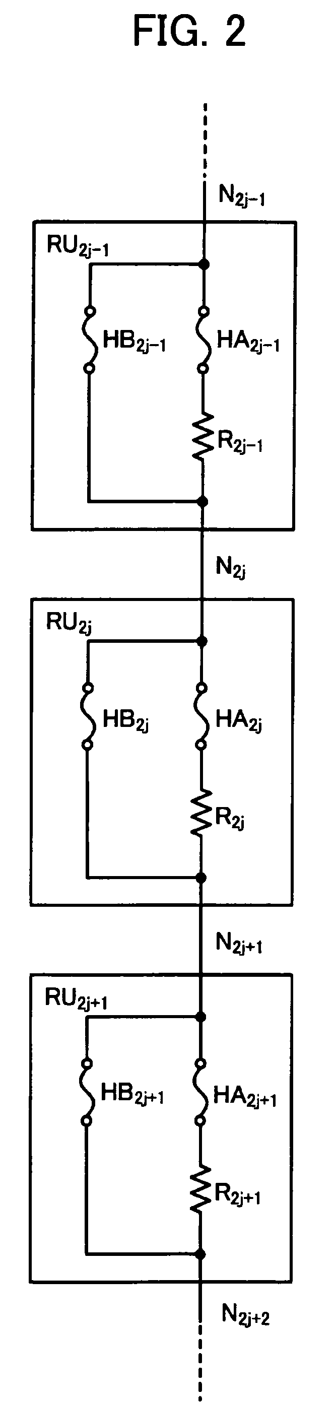
[0040]a (2j−1)th first fuse element and a (2j−1)th resistor that are provided in series between a (2j−1)th node and a 2jth node; and

[0041]a (2j−1)th second fuse element that is provided in parallel with the (2j−1)th first fuse element and the (2j−1)th resistor between the (2j−1)th node and the 2jth node;

[0042]a 2jth resistor circuit unit among the first to Mth resistor circuit units including:

[0043]a 2jth first fuse element and a 2jth resistor th...


PUM


Abstract

A resistor circuit includes first to Mth resistor circuit units. A (2j−1)th resistor circuit unit includes a (2j−1)th first fuse element and a (2j−1)th resistor provided in series between a (2j−1)th node and a 2jth node, and a (2j−1)th second fuse element provided in parallel with the (2j−1)th first fuse element and the (2j−1)th resistor between the (2j−1)th node and the 2jth node. A 2jth resistor circuit unit includes a 2jth first fuse element and a 2jth resistor provided in series between the 2jth node and a (2j+1)th node, and a 2jth second fuse element that is provided in parallel with the 2jth first fuse element and the 2jth resistor between the 2jth node and the (2j+1)th node. The (2j−1)th first fuse element, the (2j−1)th second fuse element, the 2jth first fuse element, and the 2jth second fuse element are disposed in a fuse region. The (2j−1)th resistor is disposed in a first resistor region formed in a first direction with respect to the fuse region. The 2jth resistor is disposed in a second resistor region formed in a third direction with respect to the fuse region, the third direction being a direction opposite to the first direction.

Description

[0001]Japanese Patent Application No. 2007-39669 filed on Feb. 20, 2007, is hereby incorporated by reference in its entirety.BACKGROUND OF THE INVENTION[0002]The present invention relates to a resistor circuit, an oscillation circuit, and the like.[0003]A CR oscillation circuit is used as a circuit which generates a clock signal used in an integrated circuit device. The CR oscillation circuit includes a feedback resistor, a feedback capacitor, and a plurality of stages of inverter circuits.[0004]The frequency of the clock signal generated by the CR oscillation circuit is set based on the resistance of the feedback resistor and the capacitance of the feedback capacitor. Therefore, it is necessary to accurately adjust the resistance of the feedback resistor in order to increase the accuracy of the frequency of the clock signal generated. A resistor circuit having fuse elements may be used as the feedback resistor. Specifically, the resistance of the feedback resistor is variably adjus...

Claims


Application Information

Patent Timeline
Patent Type & Authority Patents(United States)
IPC IPC(8): H01C10/00
CPCH01L23/5256H01L23/5258H03K3/03G11C17/16G11C17/18H01C1/16H01C13/02H01L2924/00H01L2924/0002
Inventor ONISHI, KOTA
Owner SEIKO EPSON CORP
Why Eureka
Try Eureka