Magneto-resistive effect device of the CPP structure and magnetic disk system

a magnetic disk and resistance technology, applied in the field of magnetoresistive effect devices, can solve the problems of limited operation current and decreasing heat dissipation efficiency with decreasing area

Active Publication Date: 2010-11-02
TDK CORPARATION
View PDF11 Cites 11 Cited by
  • Summary
  • Abstract
  • Description
  • Claims
  • Application Information

AI Technical Summary

Benefits of technology

[0014]According to the present invention, the aforesaid object is accomplishable by the provision of a magneto-resistive effect device of the CPP (current perpendicular to plane) structure, comprising a magneto-resistive effect unit, and an upper shield layer and a lower shield layer located and formed with that magneto-resistive effect unit sandwiched between them, with a sense current applied in a stacking direction, wherein said magneto-resistive effect unit comprises a nonmagnetic metal intermediate layer, and a first ferromagnetic layer and a second ferromagnetic layer stacked and formed with that nonmagnetic metal intermediate layer sandwiched between them, wherein said first ferromagnetic layer and said second ferromagnetic layer are exchange coupled via the nonmagnetic metal intermediate layer such that where there is no bias magnetic field applied, their magnetizations are anti-parallel with each other, and at least one of said upper shield layer and said lower shield layer has an inclined magnetization structure with its magnetization inclining with respect to a track width direction, so that by magnetization of that inclined magnetization structure, a bias magnetic field can be applied to said first ferromagnetic layer and said second ferromagnetic layer, wherein said inclined magnetization structure has a degree of inclination of magnetization such that while said upper shield layer and said lower shield layer maintain their own shield function, substantial orthogonal intersection of magnetization of said first ferromagnetic layer and magnetization of said second ferromagnetic layer is achievable.

Problems solved by technology

As the reproducing head track grows narrow with a decreasing device height, so does the device area; however, with the prior art structure, there is an operating current limited from the standpoint of reliability, because there is heat dissipation efficiency decreasing with a decreasing area.

Method used


Image

  • Magneto-resistive effect device of the CPP structure and magnetic disk system
  • Magneto-resistive effect device of the CPP structure and magnetic disk system
  • Magneto-resistive effect device of the CPP structure and magnetic disk system

Examples


experimental examples

[0143]The invention is now explained in further details with reference to some specific examples of the inventive magneto-resistive effect device.

experimental example 1

[0144]Experimentation was carried out to learn what influences the angle θ of magnetization of the inclined magnetization structure formed at the upper shield layer and the thickness h (see FIG. 3) of the upper shield layer had on the bias magnetic field generated (leaking) from the upper shield layer.

[0145]The angle θ of magnetization was changed to 5°, 10°, 15°, 20°, 25°, 30°, 35°, 40°, 45°, 55°, 70°, and 90°, respectively, and the thickness h of the upper shield layer was changed to 5 nm, 100 nm, and 200 nm, respectively.

[0146]The results are plotted in the graph of FIG. 13 with the angle θ of magnetization as abscissa and the bias magnetic field leaking from the upper shield layer as ordinate. The parameter is the thickness h of the upper shield layer. It is seen that as the angle θ of magnetization increases, so does the bias magnetic field. It is seen that when the angle θ of magnetization is 45°, a bias magnetic field of about 600 Oe is applied, and that even at an angle θ of...

experimental example 2

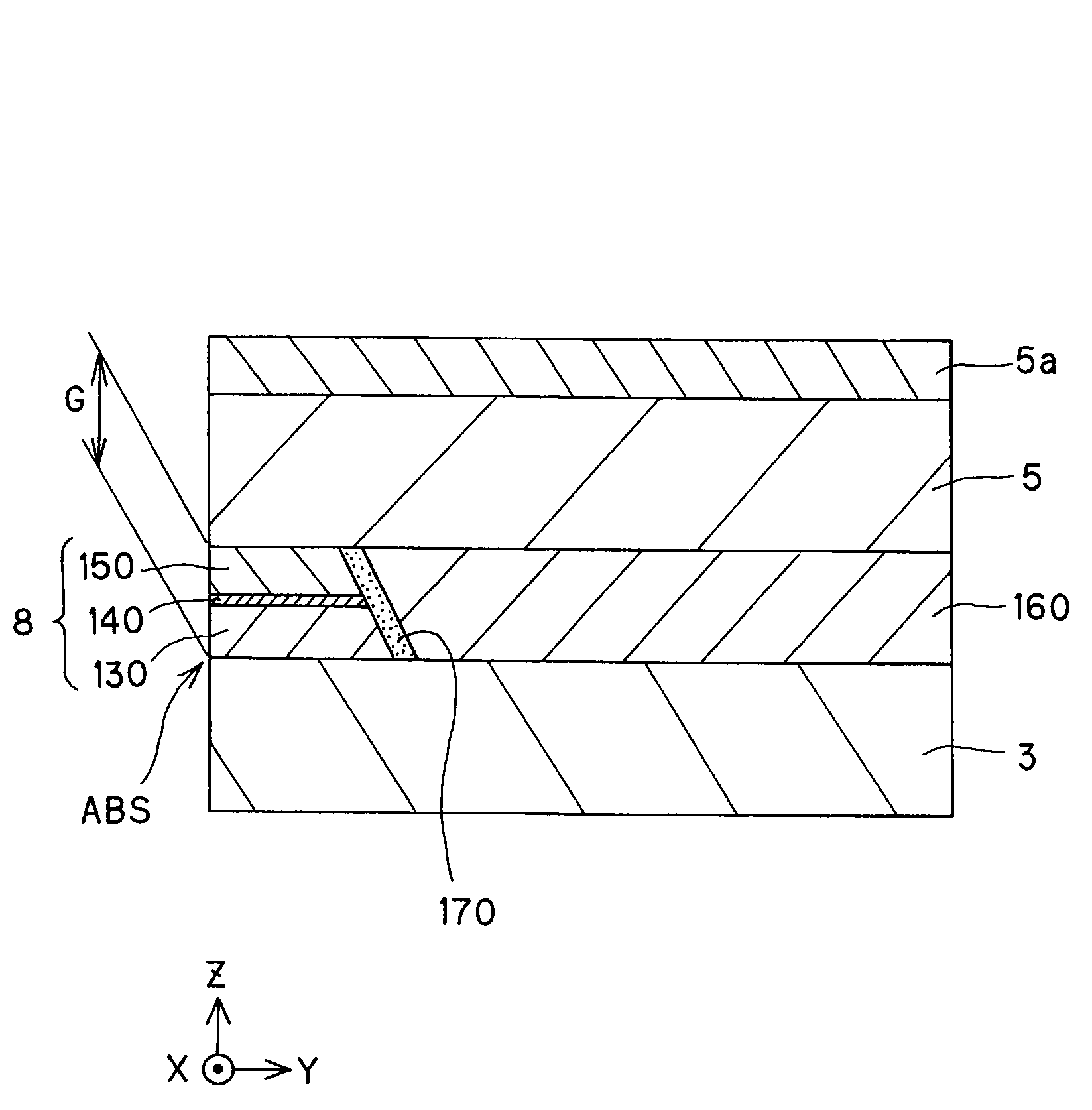
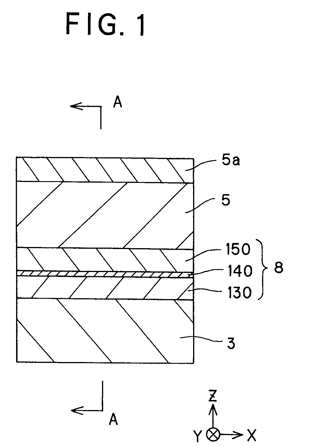
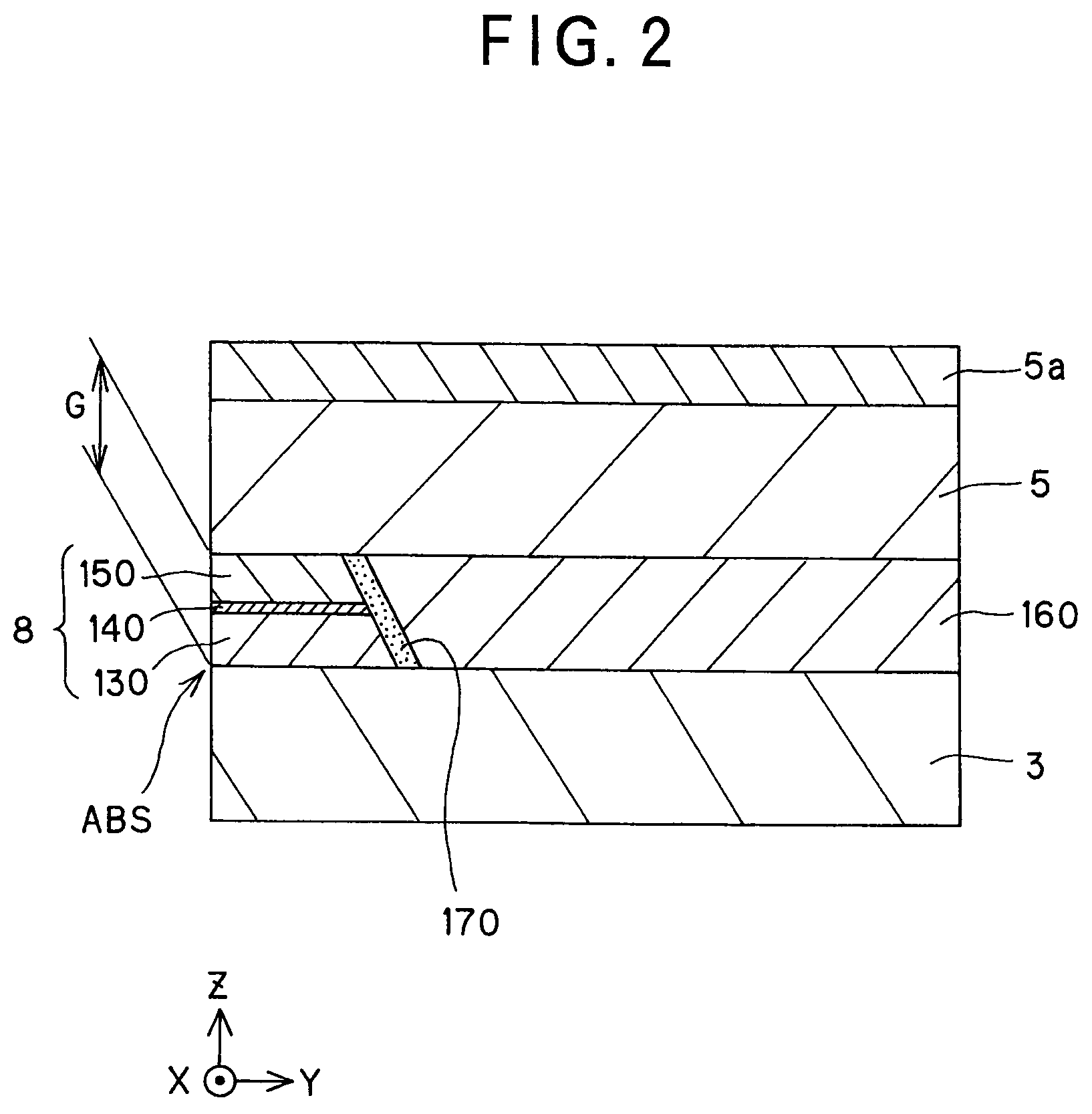
[0148]As shown in Table 1, the magneto-resistive effect unit 8 was formed on the lower shield layer 3 made of a 100-nm thick NiFe, the upper shield layer 5 made of a 100-nm thick NiFe was formed on that magneto-resistive effect unit 8, and the antiferromagnetic member 5a made of IrMn was formed on that upper shield layer 5.

[0149]The magneto-resistive effect device 8 was formed such that the first ferromagnetic layer 130 made of a 5-nm thick CoFe and the second ferromagnetic layer 150 made of a 5-nm thick CoFe were exchange coupled to each other via the nonmagnetic metal intermediate layer 140 made of a 1.0-nm thick Cu.

[0150]By exchange coupling with the antiferromagnetic member 5a made of IrMn, the upper shield layer 5 had its angle θ of magnetization set at 45°.

[0151]As a result of using such a magnetic field sensor to detect signal magnetic fields from the medium corresponding to −400 Oe to 400 Oe, it was found that there can be a practically available magnetic resistance change o...


PUM

PropertyMeasurementUnit
magnetizationaaaaaaaaaa
thicknessaaaaaaaaaa
thicknessaaaaaaaaaa

Abstract

The invention provides a magneto-resistive effect device of the CPP (current perpendicular to plane) structure, comprising a magneto-resistive effect unit, and an upper shield layer and a lower shield layer located with that magneto-resistive effect unit sandwiched between them, with a sense current applied in a stacking direction, wherein the magneto-resistive effect unit comprises a nonmagnetic metal intermediate layer, and a first ferromagnetic layer and a second ferromagnetic layer stacked and formed with that nonmagnetic metal intermediate layer sandwiched between them, wherein the first ferromagnetic layer and said second ferromagnetic layer are exchange coupled via the nonmagnetic metal intermediate layer such that where there is no bias magnetic field applied as yet, their magnetizations are anti-parallel with each other, and at least one of the upper shield layer and the lower shield layer has an inclined magnetization structure with its magnetization inclining with respect to a track width direction, so that by the magnetization of that inclined magnetization structure, a bias magnetic field can be applied to the first ferromagnetic layer and the second ferromagnetic layer. It is thus possible to obtain a magneto-resistive effect device of improved reliability that enables a structure capable of having a narrowed read gap (the gap between the upper shield and the lower shield) to be adopted to meet the recently demanded ultra-high recording density, allows a stable bias magnetic field to be applied in simple structure, and obtain a stable magneto-resistive effect change.

Description

BACKGROUND OF THE INVENTION[0001]1. Field of the Invention[0002]The present invention relates to a magneto-resistive effect device adapted to read the magnetic field intensity of magnetic recording media or the like as signals, a thin-film magnetic head comprising that magneto-resistive effect device, and a head gimbal assembly and a magnetic disk system including that thin-film magnetic head.[0003]2. Explanation of the Prior Art[0004]In recent years, with an increase in the recording density of hard disks (HDDs), there have been growing demands for improvements in the performance of thin-film magnetic heads. For the thin-film magnetic head, a composite type thin-film magnetic head has been widely used, which has a structure wherein a reproducing head having a read-only magneto-resistive effect device (hereinafter often called the MR device for short) and a recording head having a write-only induction type magnetic device are stacked together.[0005]The magneto-resistive effect devic...

Claims


Application Information

Patent Timeline
Patent Type & Authority Patents(United States)
IPC IPC(8): G11B5/39
CPCB82Y25/00G01R33/093G11B5/1278H01F10/325G11B5/3912G11B5/3967G11B5/3116
Inventor SHIMAZAWA, KOJICHOU, TSUTOMUTSUCHIYA, YOSHIHIRO
Owner TDK CORPARATION
Why Eureka
Try Eureka