System for ventilating a combustion chamber wall in a turbomachine

a combustion chamber wall and turbomachine technology, which is applied in the direction of machines/engines, liquid fuel engines, lighting and heating apparatus, etc., can solve the problems of complex and costly modifications of the diffuser and the turbomachine casing, and the solution is not entirely satisfactory. , to achieve the effect of simple, effective and economic

Active Publication Date: 2010-11-09
SN DETUDE & DE CONSTR DE MOTEURS DAVIATION S N E C M A
View PDF10 Cites 19 Cited by
  • Summary
  • Abstract
  • Description
  • Claims
  • Application Information

AI Technical Summary

Benefits of technology

[0007]The object of the invention is in particular to provide a simple, effective and economic solution to these problems.
[0008]Accordingly, it proposes a system for ventilating a combustion chamber wall in a turbomachine comprising a centrifugal compressor supplying, via a diffuser, the combustion chamber, and an internal casing with a substantially L-shaped section that is connected to the diffuser and that extends downstream to air injection means for ventilating a turbine, wherein an annular convecting metal sheet is arranged radially between the combustion chamber and the internal casing and extends axially from the diffuser to the injection means along a radially internal wall of the combustion chamber in order to delimit, with the internal wall of the chamber, an annular stream for the flow of air without separation and with reduced pressure losses, intended to supply holes in the internal wall of the combustion chamber and the air injection means.
[0009]The annular metal sheet according to the invention provides a stable air flow without separation and with minimal pressure losses along the internal wall of the combustion chamber, which allows an optimal supply of the air injection means and of the primary and dilution orifices of the internal wall of the chamber. This convecting metal sheet has a purely aerodynamic function which the diffuser end-piece or internal casing does not have to fulfill so that the shapes of this casing and of the convecting metal sheet may be optimized independently of one another.
[0014]To make it easier to mount, the substantially cylindrical portion of the metal sheet comprises a cylindrical rim oriented away from the substantially radial portion of the metal sheet.

Problems solved by technology

However, these solutions are not entirely satisfactory because they are not particularly applicable to a combustion chamber that is inclined inward from upstream to downstream.
Also, they bring with them complex and costly modifications of the diffuser and of the casing of the turbomachine.

Method used


Image

  • System for ventilating a combustion chamber wall in a turbomachine
  • System for ventilating a combustion chamber wall in a turbomachine
  • System for ventilating a combustion chamber wall in a turbomachine

Examples


Embodiment Construction

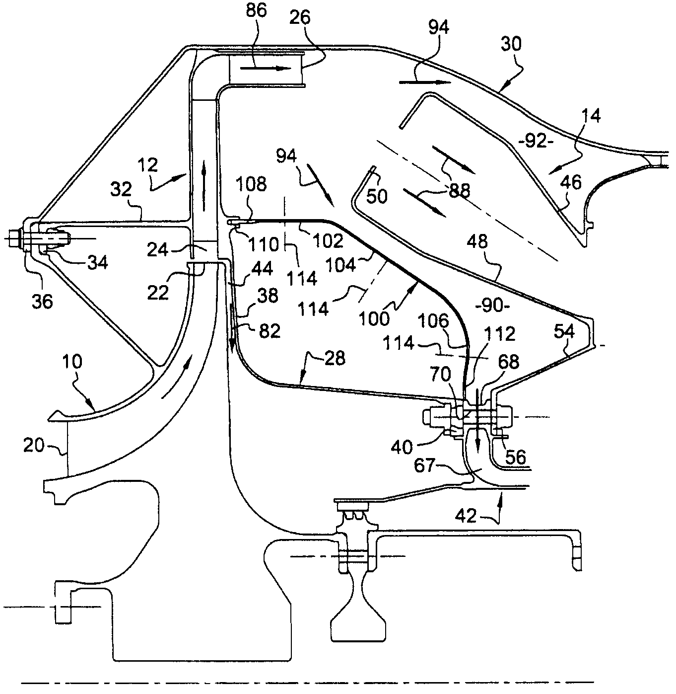
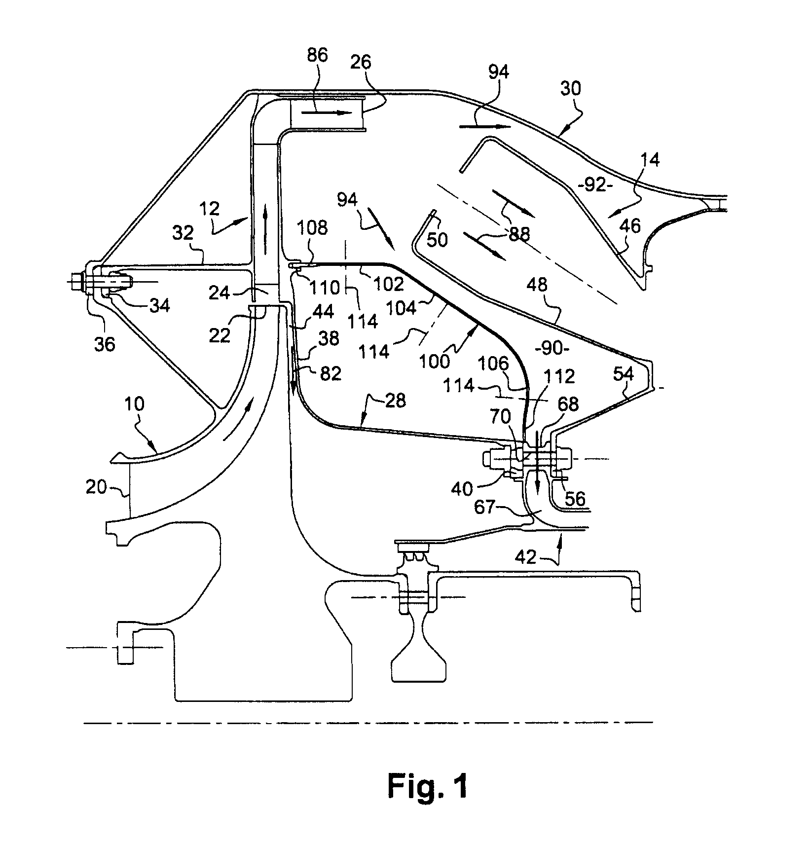
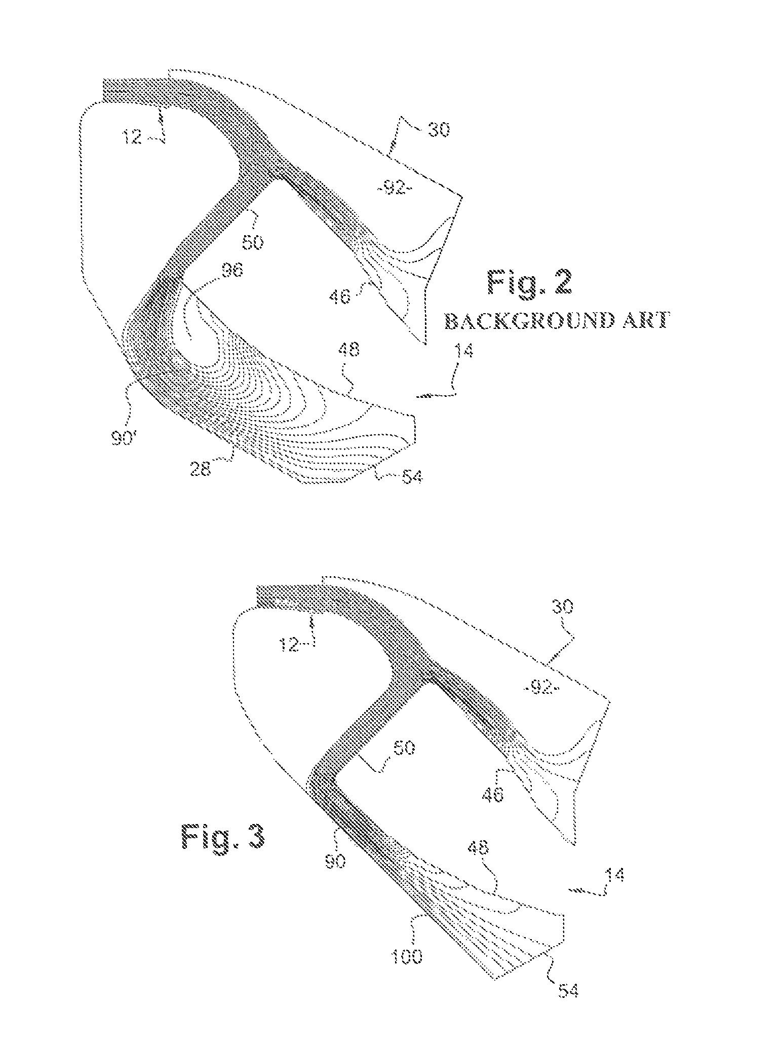
[0020]FIG. 1 represents a portion of a turbomachine, such as an aircraft turbojet or turboprop, comprising, from upstream to downstream, in the direction of flow of the gases inside the turbomachine, a centrifugal compressor 10, a diffuser 12 and a combustion chamber 14.

[0021]The inlet 20 of the centrifugal compressor 10 is oriented upstream, substantially parallel to the axis of the turbomachine, and its outlet 22 is oriented radially outward, substantially perpendicularly to the axis of the turbomachine.

[0022]The diffuser 12 has a generally annular shape bent at 90° and comprises an inlet 24 aligned with the outlet 22 of the compressor, and an outlet 26 that is oriented downstream and opens radially on the outside of the combustion chamber 14.

[0023]The diffuser 12 is supported by an external casing 30 which externally surrounds the compressor 10, the diffuser 12 and the combustion chamber 14.

[0024]The diffuser 12 comprises an upstream cylindrical ring 32 terminating in an internal...


PUM


Abstract

A system for ventilating a combustion chamber wall in a turbomachine is disclosed. The system includes a diffuser mounted at the inlet of the combustion chamber, an annular end-piece that extends downstream to an injection device for injecting ventilation air, and an annular convecting metal sheet being arranged radially between the combustion chamber and the end-piece of the diffuser in order to delimit, with an internal wall of the chamber, an annular stream for the flow of air that is stable and without separation supplying holes in the chamber and the injection device.

Description

[0001]The present invention relates to a system for ventilating a combustion chamber wall in a turbomachine comprising a centrifugal compressor and a diffuser supplying the annular combustion chamber with air.BACKGROUND OF THE INVENTION[0002]In a known manner, the annular combustion chamber of the turbomachine is situated in an annular space delimited by an internal casing and an external casing. The internal casing supports the diffuser whose inlet is aligned with the outlet of the centrifugal compressor and whose outlet is situated radially outside the combustion chamber.[0003]The air coming out of the diffuser is intended primarily to enter the combustion chamber and be mixed with fuel and then burnt, and secondarily to travel round the combustion chamber to supply primary and dilution orifices of the chamber and air injection means for ventilating and / or cooling components, particularly of a turbine, situated downstream of the combustion chamber.[0004]The diffuser is connected t...

Claims


Application Information

Patent Timeline
Patent Type & Authority Patents(United States)
IPC IPC(8): F02C1/00
CPCF23R3/26
Inventor COMMARET, PATRICE ANDREHERNANDEZ, DIDIER HIPPOLYTELOCATELLI, DAVID
Owner SN DETUDE & DE CONSTR DE MOTEURS DAVIATION S N E C M A
Why Eureka
Try Eureka