Printing apparatus including a cover holding a thermal head and a platen roller on a hinged frame

a printing apparatus and thermal head technology, applied in printing, typewriters, instruments, etc., can solve the problems of high production cost, difficult operation, and inability to meet the requirements of thermal head positioning, and achieve the effect of improving the position accuracy of thermal heads and simple constitution

Active Publication Date: 2010-11-09
ICONEX LLC +1
View PDF42 Cites 13 Cited by
  • Summary
  • Abstract
  • Description
  • Claims
  • Application Information

AI Technical Summary

Benefits of technology

[0015]It is an object of the present invention to provide a thermal printer which is capable of improving position accuracy of thermal heads with respect to platen rollers in a simple constitution.
[0018]Another printing apparatus of the present invention comprises: an apparatus main body having a rotatable open / close member; a first printing head and a first platen roller which are arranged so as to be opposed to each other via a paper transfer path and execute printing on a first face of paper, and a second printing head and a second platen roller which execute printing on the other face of the paper in the apparatus main body; first and second spring materials which are compressed based on a blocking operation of the open / close member so as to elastically press the first and second printing heads against the first and second platen rollers; lock means for locking the open / close member to a blocking position; lock releasing means for releasing the locking of the lock means; a spring material for opening which opens the open / close member by means of a spring force based on the lock releasing of the lock means by means of the lock releasing means; and decelerating means for reducing an opening speed of the open / close member released by the spring material for opening.
[0019]It is still another object of the present invention to reduce abrasion of the thermal heads and a load on a mechanism and heighten reliability.

Problems solved by technology

For this reason, the management of the position accuracy takes efforts and is expensive, and the entire thermal printer needs high production cost.
Since the open / close member is, however, opened manually by an operator totally, this operation takes efforts.
However, since the thermal heads always touch thermal recording paper, the thermal heads abrade away due to friction with thermal recording paper, and thus thermal recording paper should be frequently replaced.
Since useless load is applied to the mechanism of a driving system, malfunction easily occurs.
Since the thermal heads are expensive parts in parts composing a printer, both side printing thermal printers become more expensive than one side printing thermal printers.
For this reason, when users, who need only the one side printing at the present moment but possibly needs the both side printing later, purchase the both side printing thermal printers at first, the initial introduction cost becomes high.
On the other hand, when the one side printing thermal printer is purchased at first and the both side printing thermal printer is purchased at the time of the both side printing, it is uneconomical because the transport mechanism and the like can be shared.

Method used


Image

  • Printing apparatus including a cover holding a thermal head and a platen roller on a hinged frame
  • Printing apparatus including a cover holding a thermal head and a platen roller on a hinged frame
  • Printing apparatus including a cover holding a thermal head and a platen roller on a hinged frame

Examples


first embodiment

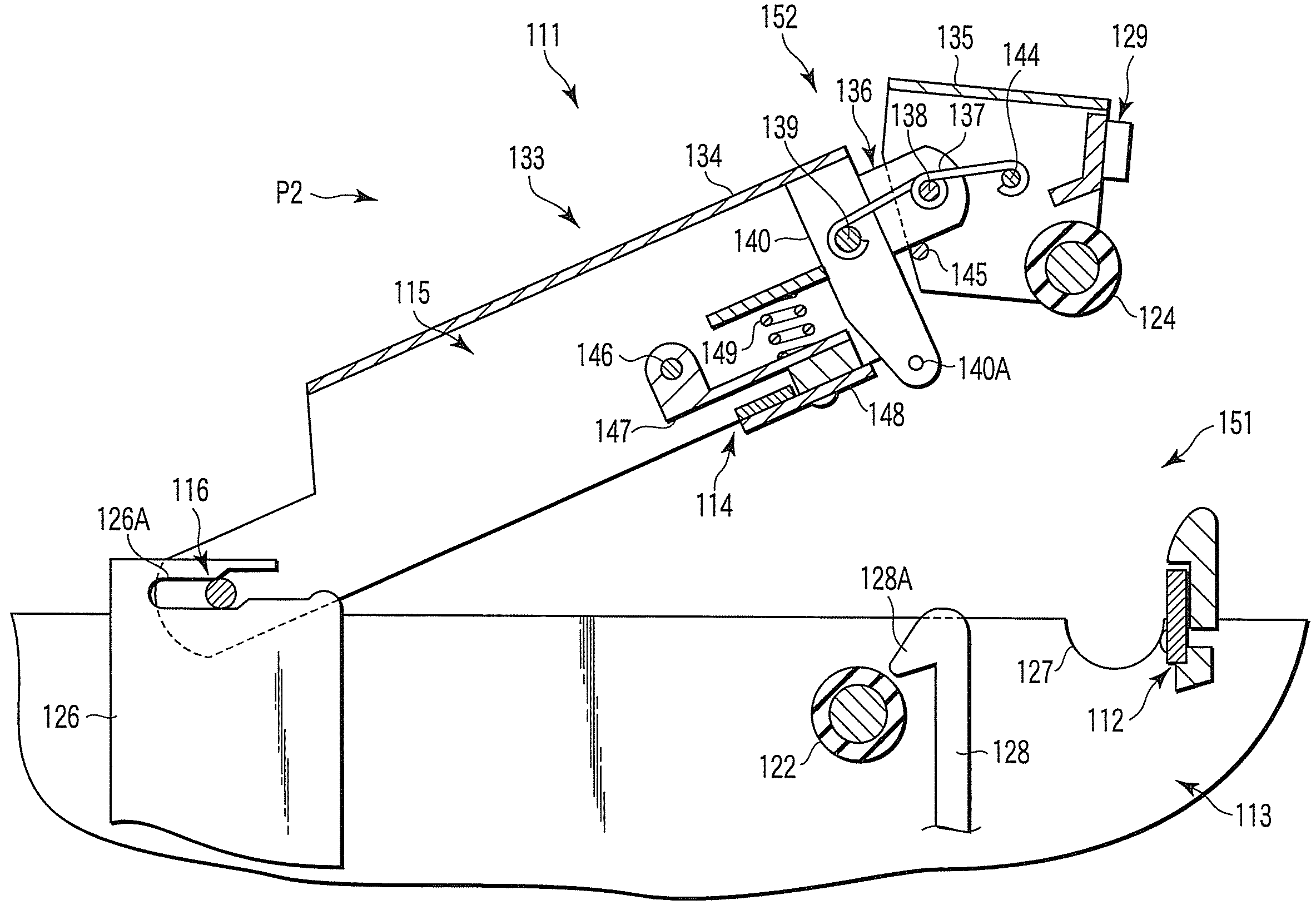
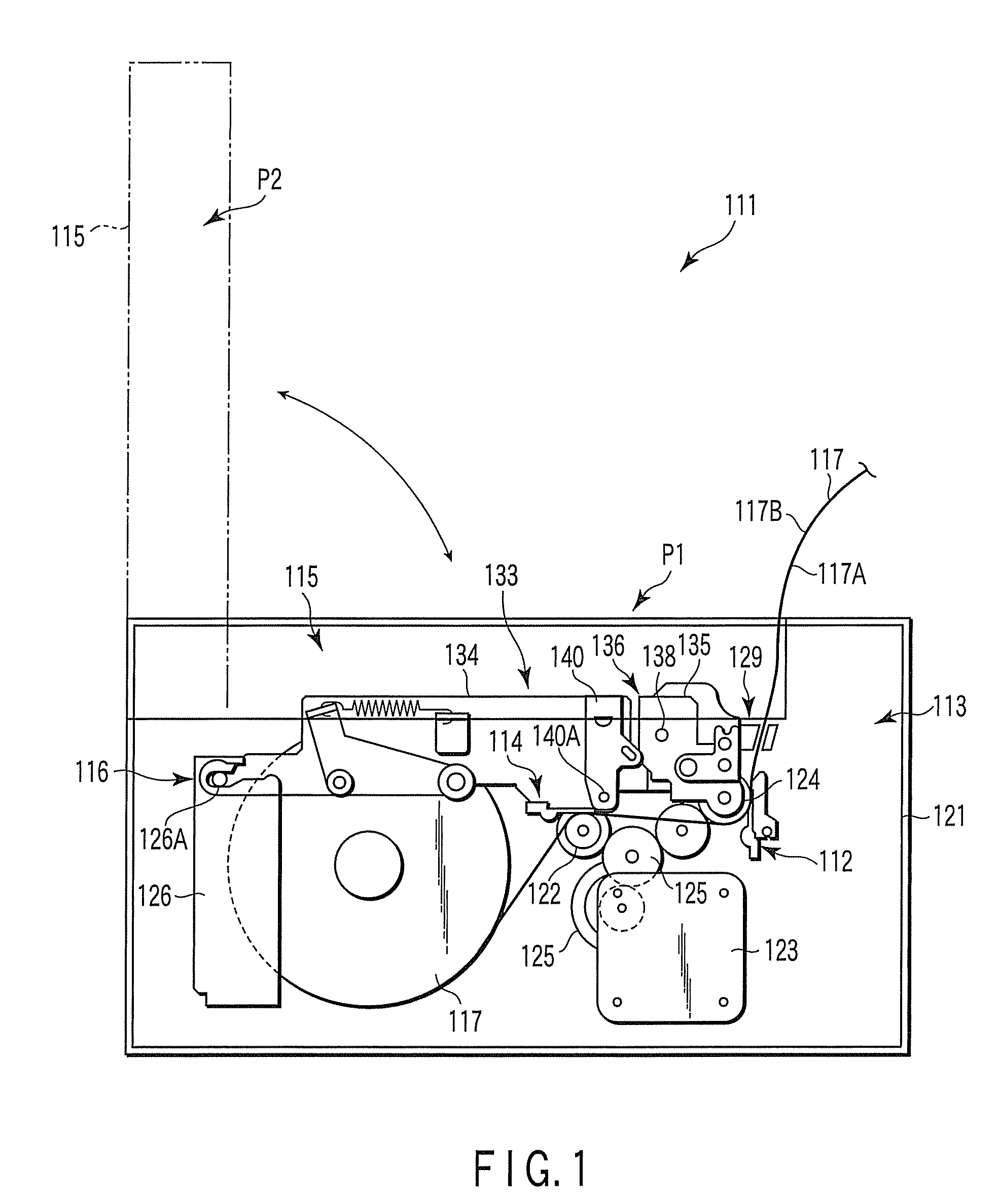
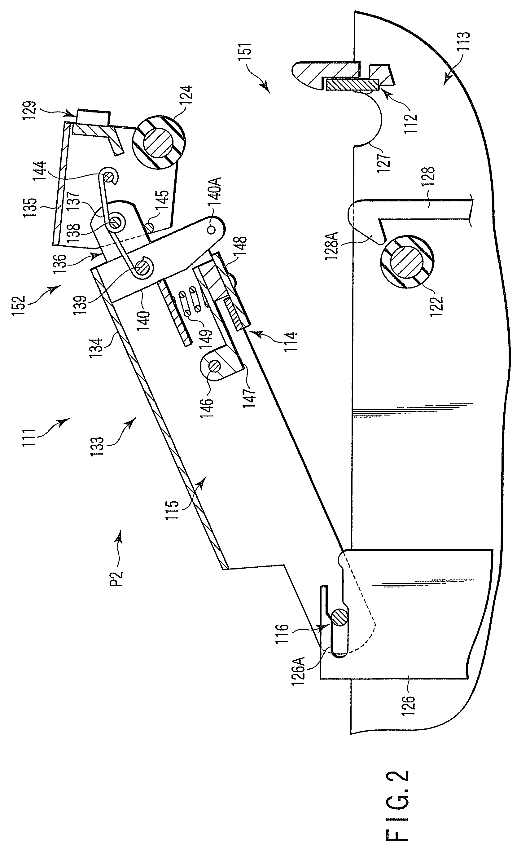
[0037]As shown in FIG. 1, a thermal printer 111 has a main body 113 having a first thermal head 112, a cover body 115 having a second thermal head 114, and a hinge mechanism 116 provided between the main body 113 and the cover body 115. The hinge mechanism 116 supports the cover body 115 so that the cover body 115 rotationally moves between a first state P1 where the cover body 115 covers the main body 113 and a second state P2 where the cover body 115 is opened with respect to the main body 113.

[0038]As shown in FIGS. 1 and 2, the main body 113 has an enclosure 121 which can enclose roll paper 117 therein, the first thermal head 112 which can execute printing on a first face 117A of the roll paper 117, a second platen roller 122 which is supported rotatably to the enclosure 121 so as to correspond to the second thermal head 114 of the cover body 115, a driving section 123 which drives feeding of the roll paper 117, a reduction gear 125 which transmits a driving force of the driving...

second embodiment

[0063]FIG. 6 illustrates a printing apparatus according to a second embodiment of the present invention. 201 in the drawing designates an apparatus main body, and a reel section 203 which supplies paper 202 is provided in the apparatus main body 201. Both faces of the paper 202 are thermal printing faces, and the paper 202 is pulled out along a paper feed path 204.

[0064]First and second printing sections 206 and 207 are disposed in the paper feed path 204. The first printing section 206 is positioned on a lower stream side of a feed direction of the paper 202, and the second printing section 207 is positioned on an upper stream side of a feed direction of the paper 202.

[0065]The first printing section 206 has a first thermal head 210 as a first printing head, and a first platen roller 211 is disposed so as to be opposed to the first thermal head 210 via the paper feed path 204. A lower side of the first thermal head 210 is rotatably supported to a main body frame side via a pivot 21...

third embodiment

[0084]FIG. 9 is a vertical sectional view schematically illustrating a both side printing thermal printer 310 according to a third embodiment of the present invention, and FIG. 10 is a side view illustrating a main section of a printing mechanism 330 incorporated into the both side printing thermal printer 310. In FIG. 9, P designates thermal recording paper having both printing faces.

[0085]The both side printing thermal printer 310 has an enclosure 311, an enclosure main body 312 for housing respective mechanisms, and an open / close cover 313 which is provided to the enclosure main body 312 so as to be opened / closed freely.

[0086]The enclosure 311 houses a thermal recording paper supply section 320 which rotatably supports a thermal recording paper roll R around which the thermal recording paper P is wound and supplies the thermal recording paper P, and a printing mechanism 330 which executes printing on the supplied thermal recording paper P.

[0087]The thermal recording paper supply ...


PUM


Abstract

A thermal printer has a main body, a cover body, a hinge mechanism, a first locating mechanism, and a second locating mechanism. At the time of a shift from a second state where the cover body is opened with respect to the main body to a first state where the cover body covers the main body, the first locating mechanism locates a first platen roller of the cover body with respect to a first thermal head of the main body, and arranges a second thermal head of the cover body in the vicinity of a second platen roller of the main body. The second locating mechanism locates the second thermal head arranged in the vicinity of the second platen roller by the first locating mechanism with respect to the second platen roller of the main body.

Description

CROSS-REFERENCE TO RELATED APPLICATIONS[0001]This application is based upon and claims the benefit of priority from prior Japanese Patent Applications No. 2006-151693, filed May. 31, 2006; No. 2006-178947, filed Jun. 29, 2006; No. 2006-178953, filed Jun. 29, 2006; and No. 2006-178958, filed Jun. 29, 2006, the entire contents of all of which are incorporated herein by reference.BACKGROUND OF THE INVENTION[0002]1. Field of the Invention[0003]The present invention relates to a printing apparatus capable of printing on both faces of roll paper.[0004]2. Description of the Related Art[0005]For example, both side printing mechanisms capable of printing simultaneously on both faces of thermal recording paper are known. In the both side printing mechanisms, a first printing section having a first thermal head and a first platen roller across a paper feed path, and a second printing section having a second thermal head and a second platen roller across the paper feed path are arranged symmetr...

Claims


Application Information

Patent Timeline
Patent Type & Authority Patents(United States)
IPC IPC(8): B41J29/02
CPCB41J2/32B41J3/60B41J15/042
Inventor NIHASHI, KIYOTAKAEOKA, KENJITAKAHASHI, KOUSUKEHIYOSHI, TAKESHISANADA, TSUYOSHISUZUKI, AKIRA
Owner ICONEX LLC
Why Eureka
Try Eureka