
Energy efficient wireless sensor network, node devices for the same and a method for arranging communications in a wireless sensor network

a wireless sensor and wireless sensor technology, applied in the direction of wireless commuication services, network planning, power management, etc., can solve the problems of high low energy consumption of network scanning, and short scanning time, so as to reduce the overall power consumption of nodes and avoid prohibitively network scanning times

Active Publication Date: 2010-11-09
WIREPAS OY
View PDF8 Cites 64 Cited by
  • Summary
  • Abstract
  • Description
  • Claims
  • Application Information

AI Technical Summary

Benefits of technology

[0015]An objective of the invention is to present a communications solution for a wireless sensor network that enables reducing the overall power consumption of nodes to a level at which they do not necessarily need any batteries or other replenishable or replaceable energy sources but can scavenge their required energy from secondary sources, like vibration, ambient light, temperature differences or the like. Another objective of the invention is to present a communications solution that enables efficient network management for example by avoiding prohibitively network scanning times. Yet another objective of the invention is to present a communications solution that enables transmission power selection and / or transmission distance determination without having to repetitively measure the level of received signal power or similar explicit quantity.
[0023]In order to operate as a headnode, a node device must have more extensive capabilities than what are needed for operating as a subnode. Therefore it would appear to be logical to provide two kinds of node devices, of which some would only join a wireless sensor network as subnodes while others would take on the responsibilities of headnodes. On the other hand, because operating as a headnode consumes more energy than operating as a subnode, and because the resources of available energy may be more or less equal for all node devices (especially if the nodes scavenge energy from their environment), it is advantageous if the nodes can circulate the headnode responsibility among themselves. This is possible only if there is an “excess” of nodes that are capable of operating as a headnode. A wireless sensor network according to the invention may consist of a mixture of two types of nodes, or alternatively of nodes of one type only that are all capable of operating as headnodes if required.

Problems solved by technology

The main source of difficulties on the route towards minimized power consumption in wireless sensor networks is traditionally the communications protocol that determines the amount and nature of wireless transmissions between the nodes.
Clearly, network scanning consumes a high amount of energy.
This short scanning time keeps energy consumption quite low.
Clearly, the consumed energy for network scanning may be very high.
The disadvantages are high performance requirements for each network node and the support for only limited mobility.
The disadvantage is that LCA utilizes a global TDMA frame structure, which requires a global clock.
Additionally since the nodes are only aware of their neighboring clusters, multi-hop routing is not supported.
Consequently, the cluster heads have a shorter battery life than other nodes, which may reduce the overall network lifetime.
A drawback is that the network scalability is limited by the coverage and the performance of the base station.
All known protocol suggestions include drawbacks that make the unsuitable for use as the communications protocol for the ultimate low-power wireless sensor network.
Many of them simply require too many transmissions to qualify as truly low-power solutions.
In others, the time a node typically needs for network scanning is prohibitively long.
One specific problem that arise in many otherwise advanced protocols is that they require using rather complex hardware at each node, for example for repetitively measuring and storing multiple RSSI (Received Signal Strength Indicator) values.

Method used


Image

  • Energy efficient wireless sensor network, node devices for the same and a method for arranging communications in a wireless sensor network
  • Energy efficient wireless sensor network, node devices for the same and a method for arranging communications in a wireless sensor network
  • Energy efficient wireless sensor network, node devices for the same and a method for arranging communications in a wireless sensor network

Examples


Embodiment Construction

[0041]The following description will discuss various aspects of the present invention in more detail.

Network Topology

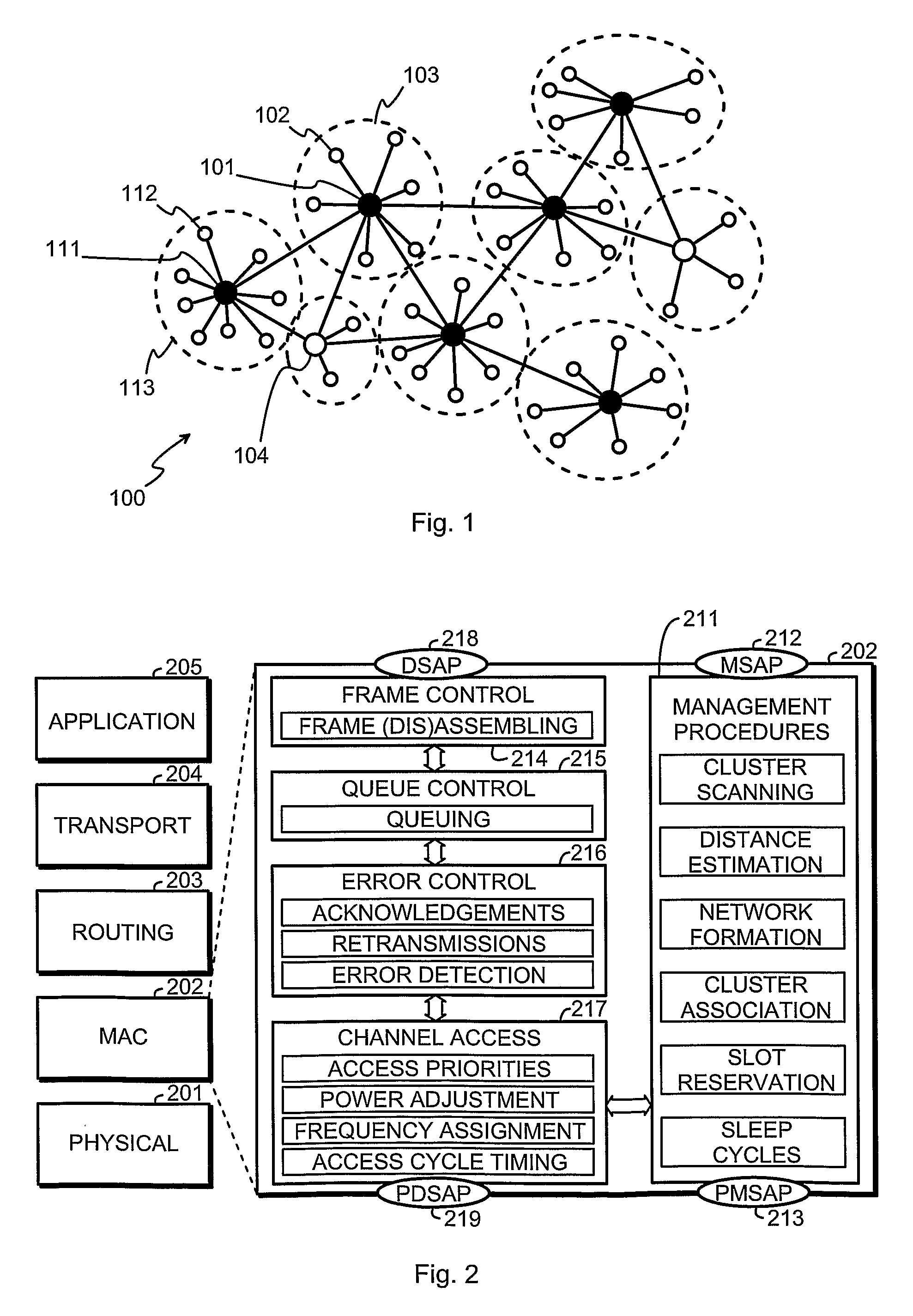
[0042]FIG. 1 is an exemplary graphical illustration of the topology of a wireless sensor network 100 according to an embodiment of the invention. There are a number of nodes that act as headnodes, shown as black circles, like headnodes 101 and 111. Each headnode has one or more subnodes 102 or 112, shown as small white circles, that communicate directly with the headnode. Together a headnode and the subnodes that communicate directly with said headnode constitute a cluster 103 or 113. Communications between clusters take place through peer to peer connections between the headnodes. Multi-hopping is supported and enables basically communications between an arbitrarily selected pair of nodes in the network.

[0043]Some of the nodes may act as sink nodes, meaning that they are users of information (while the other nodes are primarily producers of information) and may provi...


PUM


Abstract

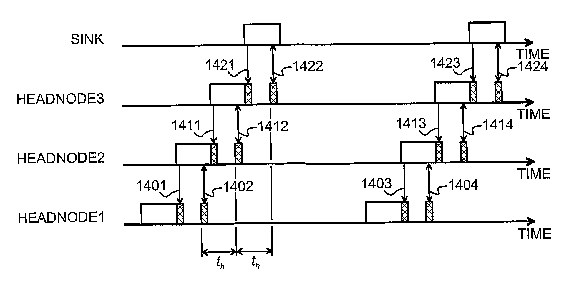
A wireless sensor network, a node device thereof and a method for arranging communications therein are presented. A first frequency is used in wireless communication of information between a headnode and subnodes of a first cluster (103) using a time slotted channel access scheme. A headnode of a second cluster (113) known the first frequency and selects a second, different frequency for use in wireless communication of information within said second cluster (113) using a time slotted channel access scheme. The headnode of the first cluster (103) is informed about the second frequency selected for the second cluster (113). Information from the headnode of said first cluster (103) to the headnode of said second cluster (113) is communicated on said second frequency, using the same time slotted channel access scheme as other nodes in said second cluster (113).

Description

TECHNICAL FIELD[0001]The invention concerns generally the technology of wireless sensor networks. Especially the invention concerns optimizing the overall power consumption of a wireless sensor network, primarily through means of finding communications protocols and arrangements that strike an effective balance between required information throughput and energy consumed for transmitting and receiving information.BACKGROUND OF THE INVENTION[0002]A wireless sensor network (WSN) is a special case of wireless networks, the specific characteristics thereof including generally very strict requirements for minimizing the physical size and power consumption of node devices, as well as specialized roles for the nodes: a large majority of the nodes are sensors that collect information and convey it to certain data sink nodes, which are few in number and may act as gateways that pass the collected information to other networks and systems. Wireless sensor networks have frequently an ad-hoc nat...

Claims


Application Information

Patent Timeline
Patent Type & Authority Patents(United States)
IPC IPC(8): H04L12/28H04BH04L12/56H04L29/08H04W16/14H04W52/02H04W72/02H04W74/00H04W74/04H04W84/18
CPCH04W16/14H04L67/04H04L67/12H04W52/0216H04W52/0219H04W56/00H04W72/02H04W74/00H04W74/04H04W84/18Y02B60/50
Inventor KOHVAKKA, MIKKOHAMALAINEN, TIMO D.HANNIKAINEN, MARKO
Owner WIREPAS OY
Learn More