
Power output apparatus for hybrid vehicle

a technology of power output apparatus and hybrid vehicle, which is applied in hybrid vehicles, electrical control, instruments, etc., can solve the problems of excessive charging of accumulators like secondary batteries, significantly greater output from internal combustion engines, etc., and achieve the effect of improving emissions

Inactive Publication Date: 2010-11-16
TOYOTA JIDOSHA KK
View PDF22 Cites 7 Cited by
  • Summary
  • Abstract
  • Description
  • Claims
  • Application Information

AI Technical Summary

Benefits of technology

[0004]The power output apparatus, the automobile, and their control methods of the invention aim to prevent an accumulator like a secondary battery from being excessively charged under a drive restriction of a motor that is capable of outputting power to a drive shaft. The power output apparatus, the automobile, and their control methods of the invention also aim to ensure output of a power in the range of the drive restriction to the drive shaft under the drive restriction of the motor. The power output apparatus, the automobile, and their control methods of the invention further aim to improve the emission under the drive restriction of the motor.
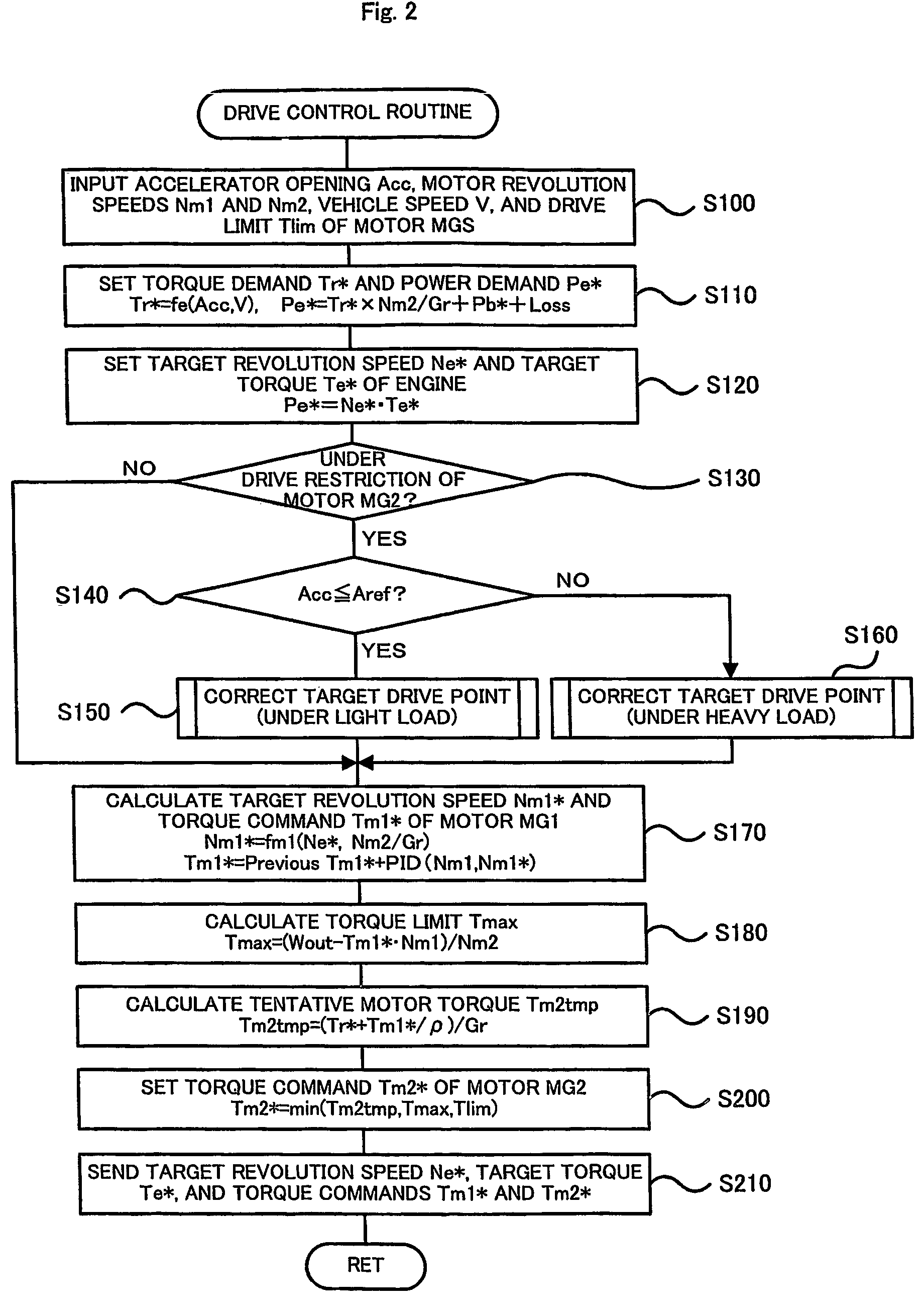
[0007]Under no drive restriction of the motor, the first power output apparatus of the invention controls the internal combustion engine, the electric power-mechanical power input-output module, and the motor to ensure output of the target power from the internal combustion engine and output of a power corresponding to the power demand to the drive shaft. Under the drive restriction of the motor, on the other hand, the first power output apparatus corrects the target power based on the drive restriction and controls the internal combustion engine, the electric power-mechanical power input-output module, and the motor to ensure output of the corrected target power from the internal combustion engine and output of a power in the drive restriction from the motor. Namely, the target power is corrected to change the drive point of the internal combustion engine under the drive restriction of the motor. The arrangement of the invention effectively prevents the accumulator from being excessively charged and ensures output of the power in the range of the drive restriction to the drive shaft. This desirably prevents deterioration of the emission by output of a power corresponding to the power demand from the internal combustion engine under the drive restriction of the motor.
[0008]In one preferable embodiment of the invention, the first power output apparatus further includes a charge-discharge electric power measurement module that measures a charge-discharge electric power used to charge the accumulator or obtained by discharging the accumulator; and an electric power demand setting module that sets an electric power demand for charging or discharging the accumulator, based on a predetermined charge-discharge condition. The correction module corrects the target power to cancel a difference between the charge-discharge electric power measured by the charge-discharge electric power measurement module and the electric power demand set by the electric power demand setting module. The electric power used to charge the accumulator or obtained by discharging the accumulator thus significantly approaches to the electric power demand. This arrangement effectively prevents the accumulator from being excessively charged.
[0009]In one preferable application of the first power output apparatus of the invention, the target power setting module specifies a target torque and a target revolution speed to set the target power, and the correction module varies the specified target revolution speed to correct the target power. The drive point of the internal combustion engine is thus changed, while the torque output from the internal combustion engine is kept unchanged. This arrangement desirably reduces the effects of a varying output of the power to the drive shaft by the electric power-mechanical power input-output module with a variation in target power.
[0012]Under no drive restriction of the motor, the second power output apparatus of the invention controls the internal combustion engine, the electric power-mechanical power input-output module, and the motor to ensure output of the target power from the internal combustion engine and output of a power corresponding to the power demand to the drive shaft. Under the drive restriction of the motor, on the other hand, the second power output apparatus corrects the target power based on the drive restriction and controls the internal combustion engine, the electric power-mechanical power input-output module, and the motor to ensure output of the corrected target power from the internal combustion engine and output of a power in the drive restriction from the motor. Namely, the target power is corrected to change the drive point of the internal combustion engine under the drive restriction of the motor. The arrangement of the invention effectively prevents the accumulator from being excessively charged and ensures output of the power in the range of the drive restriction to the drive shaft. This desirably prevents deterioration of the emission by output of a power corresponding to the power demand from the internal combustion engine under the drive restriction of the motor.

Problems solved by technology

When the motor that outputs power to the drive shaft is under a drive restriction due to heat generation in the motor or its driving circuit, however, the technique of keeping the power demand to be output from the internal combustion engine unchanged may make the output from the internal combustion engine significantly greater than the output to the drive shaft and may cause an accumulator like a secondary battery to be excessively charged.

Method used


Image

  • Power output apparatus for hybrid vehicle
  • Power output apparatus for hybrid vehicle
  • Power output apparatus for hybrid vehicle

Examples


Embodiment Construction

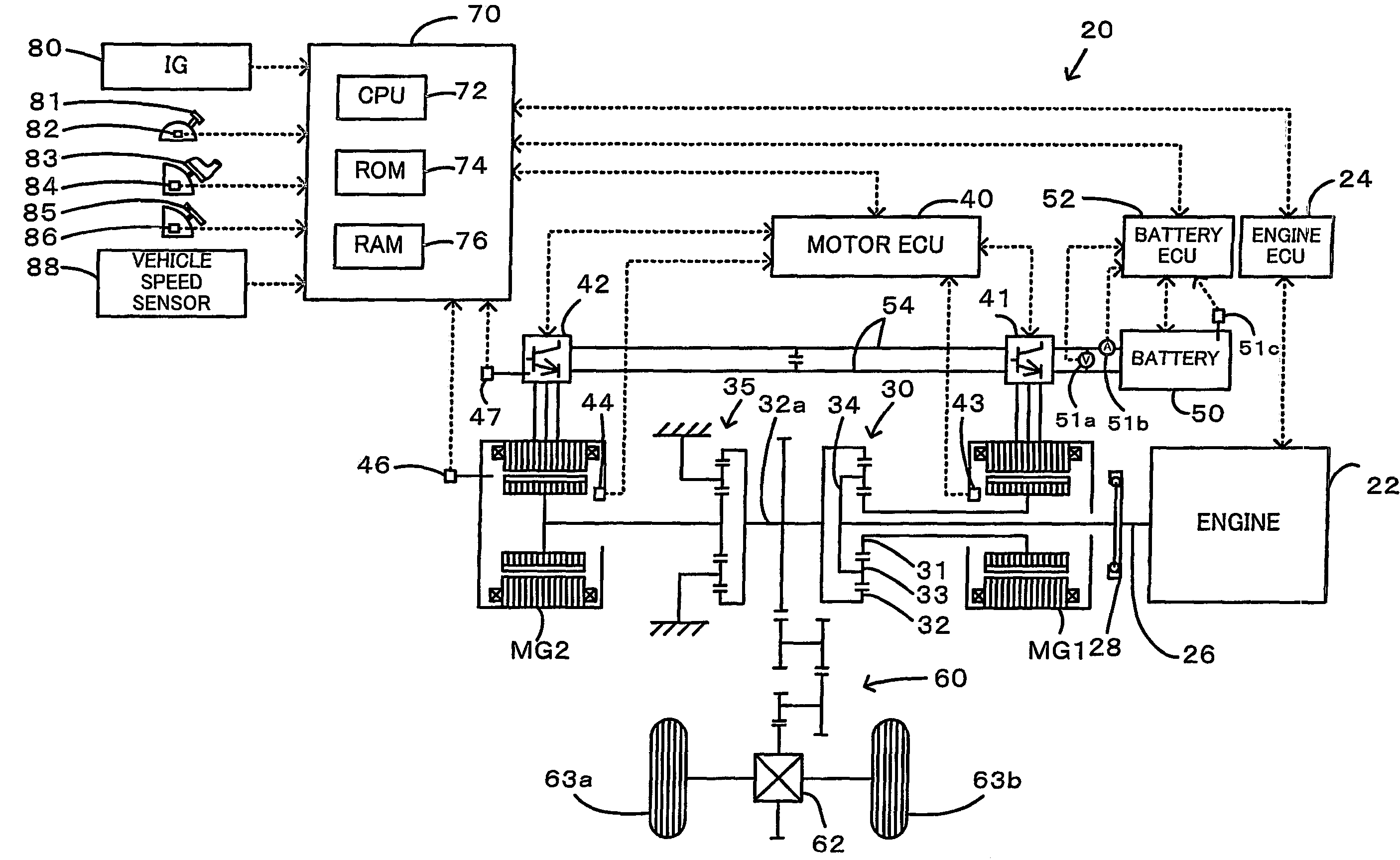
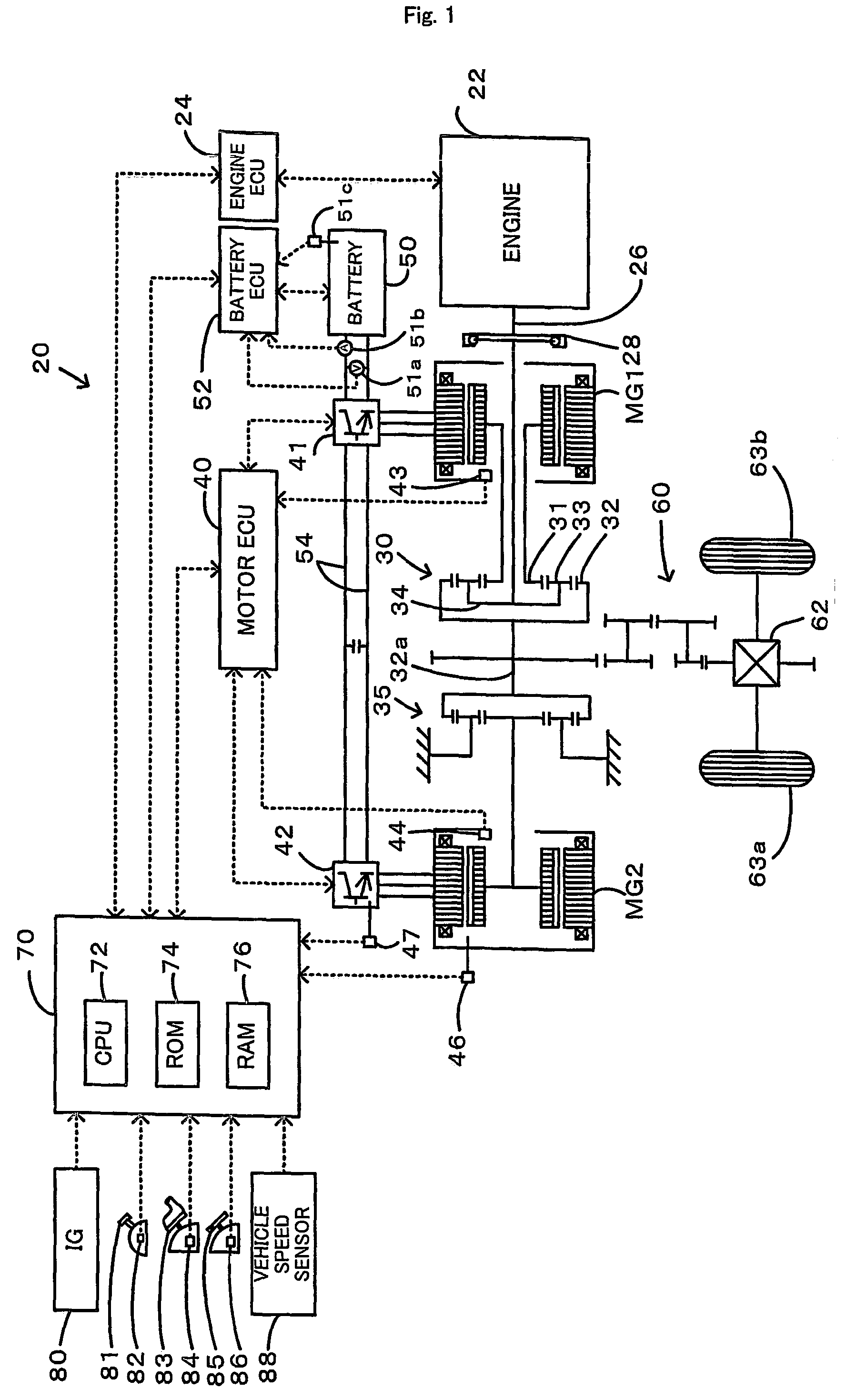
[0030]One mode of carrying out the invention is discussed below as a preferred embodiment. FIG. 1 schematically illustrates the construction of a hybrid vehicle 20 with a power output apparatus mounted thereon in one embodiment of the invention. As illustrated, the hybrid vehicle 20 of the embodiment includes an engine 22, a three shaft-type power distribution integration mechanism 30 that is linked with a crankshaft 26 functioning as an output shaft of the engine 22 via a damper 28, a motor MG1 that is linked with the power distribution integration mechanism 30 and is capable of generating electric power, a reduction gear 35 that is attached to a ring gear shaft 32a functioning as a drive shaft connected with the power distribution integration mechanism 30, another motor MG2 that is linked with the reduction gear 35, and a hybrid electronic control unit 70 that controls the whole power output apparatus.

[0031]The engine 22 is an internal combustion engine that consumes a hydrocarbon...


PUM


Abstract

A hybrid vehicle of the invention has an engine, a planetary gear unit including a carrier linked with rankshaft of the engine and a ring gear linked with a drive shaft, a motor MG1 inputting and outputting power to and from a sun gear of the planetary gear unit, and a motor MG2 inputting and outputting power to and from the drive shaft. During a drive of the hybrid vehicle in a light load state and under a drive restriction of the motor MG2, the hybrid vehicle corrects a target revolution speed Ne* of the engine to make a calculated average charge-discharge electric power Wbave of a battery equal to a charge-discharge electric power demand Wb*, while keeping a torque of the engine unchanged (steps S300 to S330), and controls actuation of the engine and the motors MG1 and MG2.

Description

FIELD OF THE INVENTION[0001]The present invention relates to a power output apparatus, an automobile, and methods of controlling the same.BACKGROUND OF THE INVENTION[0002]A proposed power output apparatus has an internal combustion engine, a planetary gear unit that includes a carrier linked with an output shaft of the internal combustion engine and a ring gear linked with a drive shaft, a generator that inputs and outputs power to and from a sun gear of the planetary gear unit, and a motor that inputs and outputs power to and from the drive shaft (see, for example, Japanese Patent Laid-Open Gazette No. H11-55810). In the case of heat generation in the generator or its driving circuit, this prior art apparatus decreases the output torque of the internal combustion engine and raises the revolution speed of the internal combustion engine, so as to reduce the load of the generator and prevent the heat generation in the generator while maintaining a power demand to be output from the in...

Claims


Application Information

Patent Timeline
Patent Type & Authority Patents(United States)
IPC IPC(8): B60W10/06B60W10/08B60K6/24B60K6/26B60K6/445B60K6/448B60K6/52B60L3/00B60L50/16B60W10/26F02D29/02F02D29/06F02D41/04F02D45/00H02J7/00
CPCB60K6/365B60K6/445B60K6/448B60K6/52B60W10/06B60W10/08B60W10/26B60W20/00Y02T10/6243Y02T10/6265Y02T10/6286Y02T10/6239Y02T10/62B60W10/115B60W20/13
Inventor HOSHIBA, TAKESHINADA, MITSUHIRO
Owner TOYOTA JIDOSHA KK
Learn More