Locking support assembly for casino chair

a technology for supporting assemblies and chairs, which is applied to chair supports, machine supports, furniture parts, etc., can solve the problems of cumbersome removal of floor plates, not structured to facilitate quick and easy alignment of locking surfaces, and inability to meet the needs of the user, so as to reduce the risk of sticking in the latch, facilitate rapid latching, and eliminate the need for latching time

Inactive Publication Date: 2010-11-16
GARY PLATT MFG
View PDF30 Cites 27 Cited by
  • Summary
  • Abstract
  • Description
  • Claims
  • Application Information

AI Technical Summary

Benefits of technology

[0014]Advantageously, the horizontal action of the latch block against the vertical cylindrical pin of the support plate reduces the risk of sticking in the latch. Also, tapered guide surfaces in the beam guide the pin to the latch mechanism while the support plate is inserted in the latch block, facilitating rapid latching and eliminating seek time for the latch point. Use of a single, centrally-disposed vertical, or substantially vertical, pin and complementary latch for the locking function, also helps reduce seek time. In addition, the centrally-disposed location of the latch mechanism and pin relative to the center of load imposed by the chair should minimize or eliminate cyclical loads on the latch and pin caused by use of the chair, causing torsion loads to be borne as compressive loading on the walls of the lower channel. The present combination of channel and latch should thus enhance the ease of use, reliability and durability of the support assembly as compared to prior lockable support assemblies.

Problems solved by technology

Locking assemblies generally require precise alignment between the latch mechanisms in the bracket and the receiving surfaces in the floorplate, but are not structured to facilitate quick and easy alignment of the locking surfaces while handling the casino chair and support plate.
In addition, some prior art designs require pulling and / or tilting the floorplate while simultaneously operating a key, making removal of the floorplate more cumbersome than desired.

Method used


Image

  • Locking support assembly for casino chair
  • Locking support assembly for casino chair
  • Locking support assembly for casino chair

Examples


Embodiment Construction

[0027]In the detailed description that follows, like element numerals are used to indicate like elements appearing in the figures.

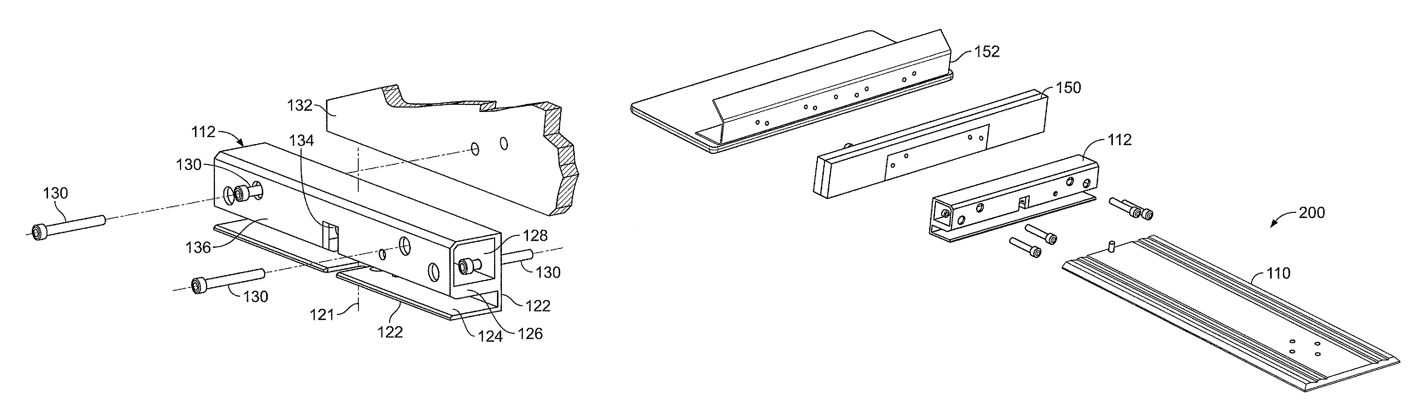
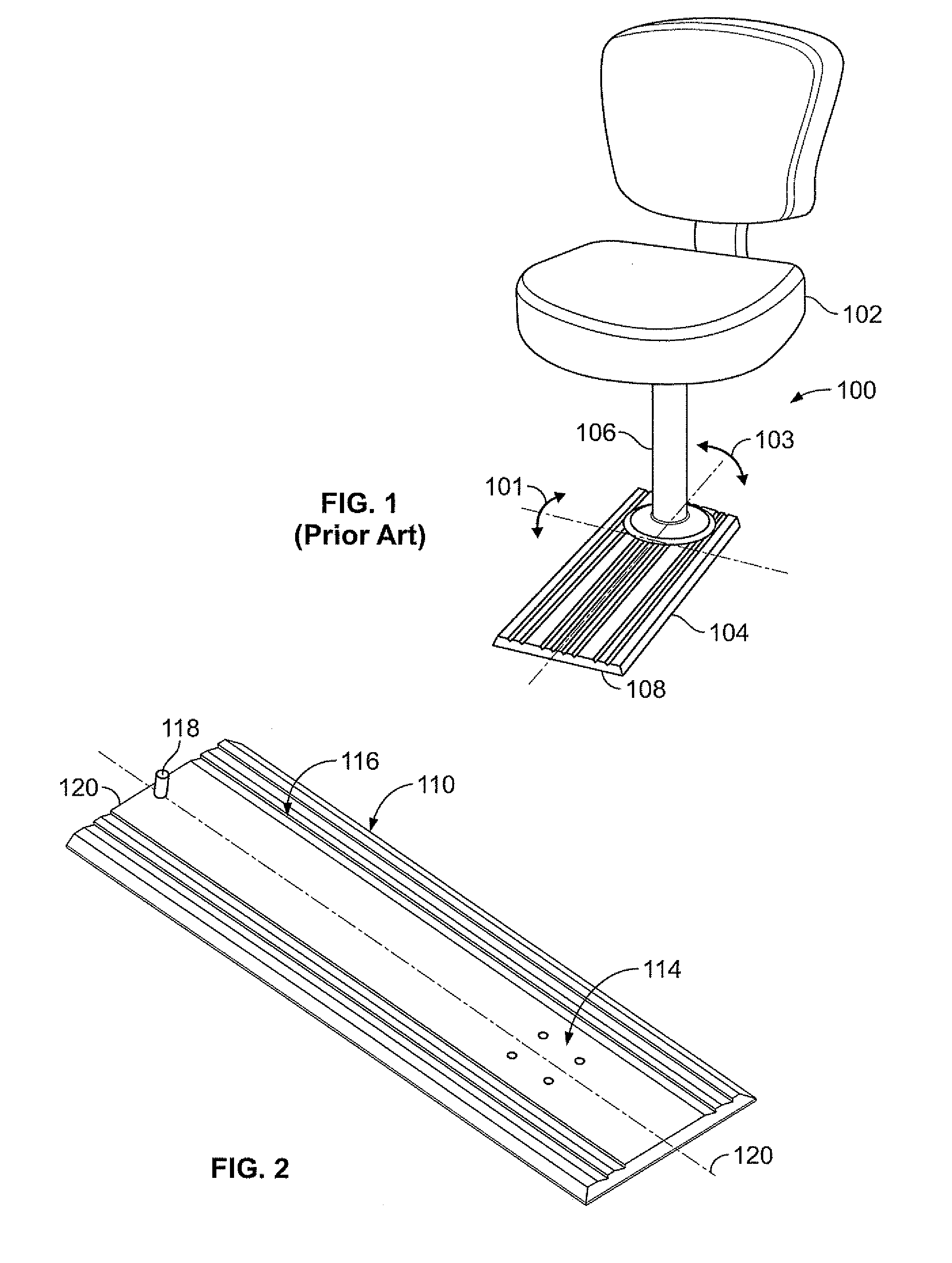
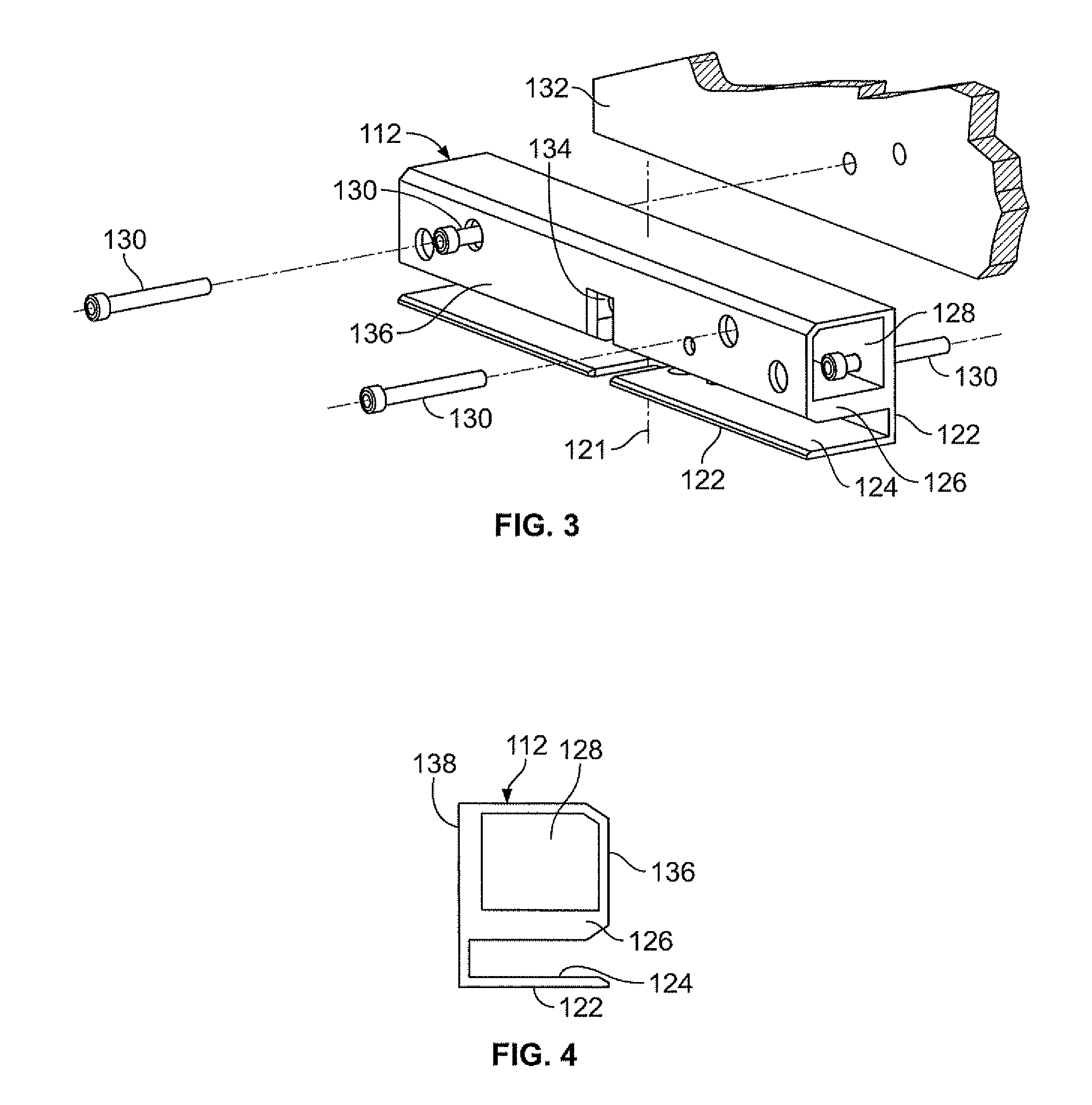
[0028]A locking support assembly for a casino chair comprises a support plate 110 as shown in FIG. 2, coupled to a beam 112, also called a latch block, as shown in FIGS. 3-6. The support plate 110 may comprise a generally planar rectangular piece of aluminum, steel or other durable material, having a receiver 114 for a chair disposed at an upper surface 116 of thereof. The plate may be machined out of extruded or other stock material. The receiver may comprise a pattern of mounting holes, as shown, or any other suitable structure for mounting a chair column to the support plate. The support plate may be eight to thirty-six inches in width and 0.2 to 1.0 inches thick, depending on the choice of materials, number of chairs supported, plate configuration, length and desired appearance. In an exemplary embodiment, the support plate comprised a solid aluminum ...


PUM


Abstract

A locking support assembly for a casino chair uses a support plate with a chair mount having a fixed pin protruding upwards from the support plate opposite to the mount. The pin may serve as a sole or primary guide member in the support plate to guide the support plate into horizontal alignment with a latch mounted inside a beam. The beam holds the support plate in close but unlocked engagement by a lower groove, to resist loads imposed by an attached chair. A releasable latch inside the beam receives the pin to provide locked engagement between the support plate and the beam. The beam may be fastened to a vertical surface of a gaming machine or other object. The support plate and attached chair can be released from the beam by inserting a tool through a keyhole in the beam to release the latch, while pulling the support plate outwards.

Description

CROSS-REFERENCE TO RELATED APPLICATION[0001]This application claims priority pursuant to 35 U.S.C. §119(e) to U.S. provisional application Ser. No. 61 / 021,283, filed Jan. 15, 2008, which application is specifically incorporated herein, in its entirety, by reference.BACKGROUND[0002]1. Field[0003]The present disclosure relates to locking support assemblies for supporting casino chairs and locking such chairs to gaming machines or other fixed locations.[0004]2. Description of Related Art[0005]Casino operators often desire chairs for gaming machines, such as, for example, slot machines, to be attached to the machine or to a location adjacent to the machine. This promotes a more orderly and safer casino by preventing inappropriate use or movement of casino chairs. Many jurisdictions require casino operators to use fixed or attached chairs. At the same time, casino chairs are expected to be both comfortable and exceptionally durable, maintaining an attractive appearance despite heavy, con...

Claims


Application Information

Patent Timeline
Patent Type & Authority Patents(United States)
IPC IPC(8): A47C7/62A47B83/02
CPCA47C15/004
Inventor DAVIS, JR., WENDELL R.LUNDEEN, DALE ROBERTVETTER, KAY DANIEL
Owner GARY PLATT MFG
Why Eureka
Try Eureka