Inverse optical design

a technology of ocular parameters and inverse optical design, applied in the field of patient-specific ocular parameters determination, can solve problems such as permanent damage to eye structures

Active Publication Date: 2010-11-16
THE ARIZONA BOARD OF REGENTS ON BEHALF OF THE UNIV OF ARIZONA +1
View PDF16 Cites 12 Cited by
  • Summary
  • Abstract
  • Description
  • Claims
  • Application Information

AI Technical Summary

Problems solved by technology

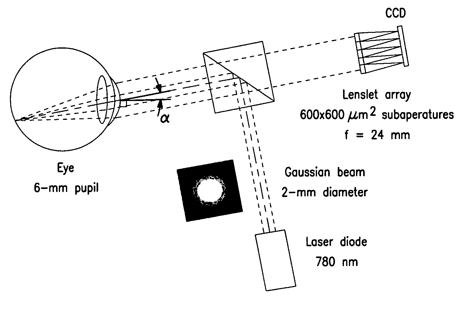
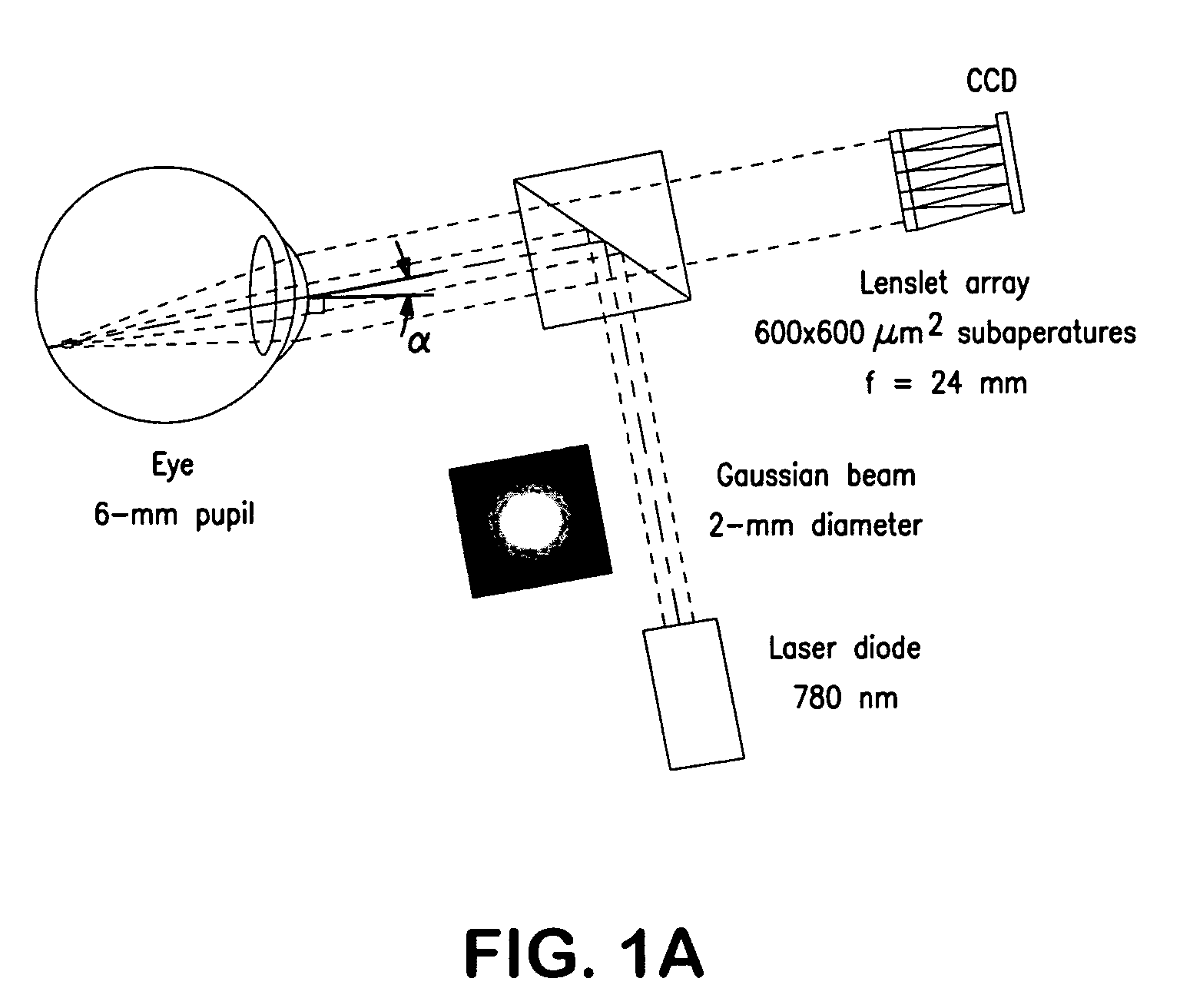
The light source may be any suitable source which illuminates at least a portion of the eye and does cause permanent damage to the eye structures.

Method used


Image

  • Inverse optical design
  • Inverse optical design
  • Inverse optical design

Examples


Embodiment Construction

[0022]The following nonlimiting description is intended to provide examples of some embodiments of this invention and further information about the operation of the invention. Applicant does not intend to be bound by the theory presented.

[0023]The term “electromagnetic radiation” and “light” are used synonymously in the present description and refer to waves of electric and magnetic fields.

[0024]“Optical communication” refers to a configuration of two or more elements wherein one or more beams of electromagnetic radiation are capable of propagating from one element to the other element. Elements in optical communication may be in direct optical communication or indirect optical communication. “Direct optical communication” refers to a configuration of two or more elements wherein one or more beams of electromagnetic radiation propagate directly from a first device element to another without use of optical components for steering and / or combining the beams. “Indirect optical communic...


PUM


Abstract

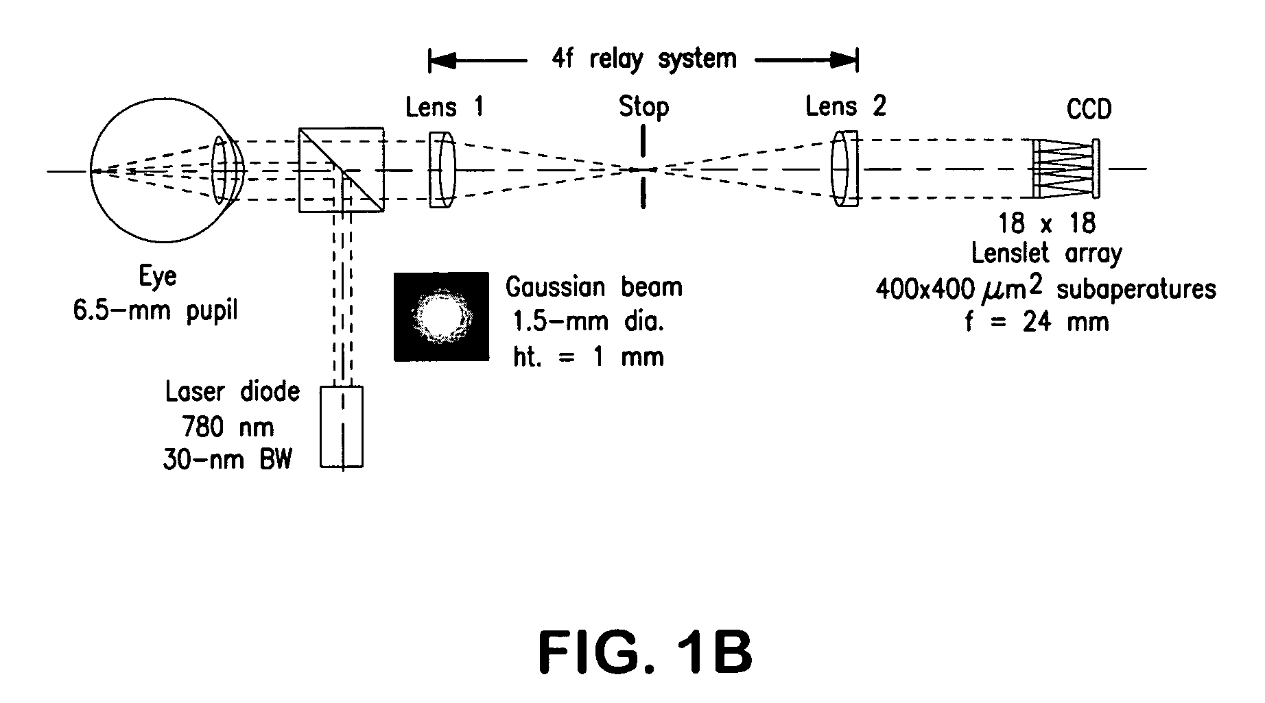
An imaging apparatus for simultaneously determining optical parameters of the eye comprising: a light source for illuminating at least a portion of the eye pupil; an illumination optical system for directing light rays emitted from the light source into the eye; a light receiving optical system for guiding the light rays reflected from the eye to a detector unit, wherein the detector unit detects an image intensity distribution from the light rays reflected from the eye; and an arithmetic unit for determining optical characteristics of the eye by parameter estimation is provided.

Description

CROSS-REFERENCE TO RELATED APPLICATIONS[0001]This application takes priority from U.S. provisional application Ser. No. 60 / 934,786, filed Jun. 15, 2007, the disclosure of which is hereby incorporated by reference to the extent not inconsistent with the disclosure herein.REFERENCE TO FEDERAL FUNDING SUPPORT[0002]This invention was made with government support under Grant Numbers R37 EB000803 and T32 EB000809 awarded by NIH. The government has certain rights in the invention.BACKGROUND OF THE INVENTION[0003]The present invention generally relates to determination of patient-specific ocular parameters. The availability of a complete patient-specific eye model would provide many advantages in vision science and ophthalmology. A patient-specific eye model could be used as a basis for vision correction of higher-order aberrations in laser refractive surgery or with corrective lenses, since classical devices only measure and correct for basic refractive errors (i.e., defocus and astigmatis...

Claims


Application Information

Patent Timeline
Patent Type & Authority Patents(United States)
IPC IPC(8): A61B3/10
CPCA61B3/1015
Inventor BARRETT, HARRISON H.SAKAMOTO, JULIA A.GONCHAROV, ALEXANDER V.
Owner THE ARIZONA BOARD OF REGENTS ON BEHALF OF THE UNIV OF ARIZONA
Why Eureka
Try Eureka