Driving mechanism

a technology of driving mechanism and motor shaft, which is applied in the direction of generator/motor, television system, instruments, etc., can solve the problems of not being able to achieve a further increase in speed, not necessarily satisfactory, and conventional structures

Inactive Publication Date: 2010-11-16
KK TOSHIBA
View PDF17 Cites 14 Cited by
  • Summary
  • Abstract
  • Description
  • Claims
  • Application Information

AI Technical Summary

Benefits of technology

[0006]However, each of these conventional structures has the following problems and is not necessarily satisfactory. (A) The arrangement in which single-axis actuators are connected in series and stacked on each other makes it difficult to achieve a further increase in speed (a decrease in rigidity) and a further decrease in size. (B) Because of large axis interference, it is difficult to simplify a controller and increase its speed and accuracy. (C) The range of movement is narrow, and hence versatility is low. The conventional structure using the parallel plate and the radiation plate has a limited range of application because of problems (A) and (C) described above in particular. The structure using the elastic hinge and the structure using the parallel mechanism have limited ranges of application mainly because of problems (B) and (C) described above.

Problems solved by technology

However, each of these conventional structures has the following problems and is not necessarily satisfactory.
(A) The arrangement in which single-axis actuators are connected in series and stacked on each other makes it difficult to achieve a further increase in speed (a decrease in rigidity) and a further decrease in size.
(B) Because of large axis interference, it is difficult to simplify a controller and increase its speed and accuracy.
The conventional structure using the parallel plate and the radiation plate has a limited range of application because of problems (A) and (C) described above in particular.
The structure using the elastic hinge and the structure using the parallel mechanism have limited ranges of application mainly because of problems (B) and (C) described above.

Method used


Image

  • Driving mechanism
  • Driving mechanism
  • Driving mechanism

Examples


first embodiment

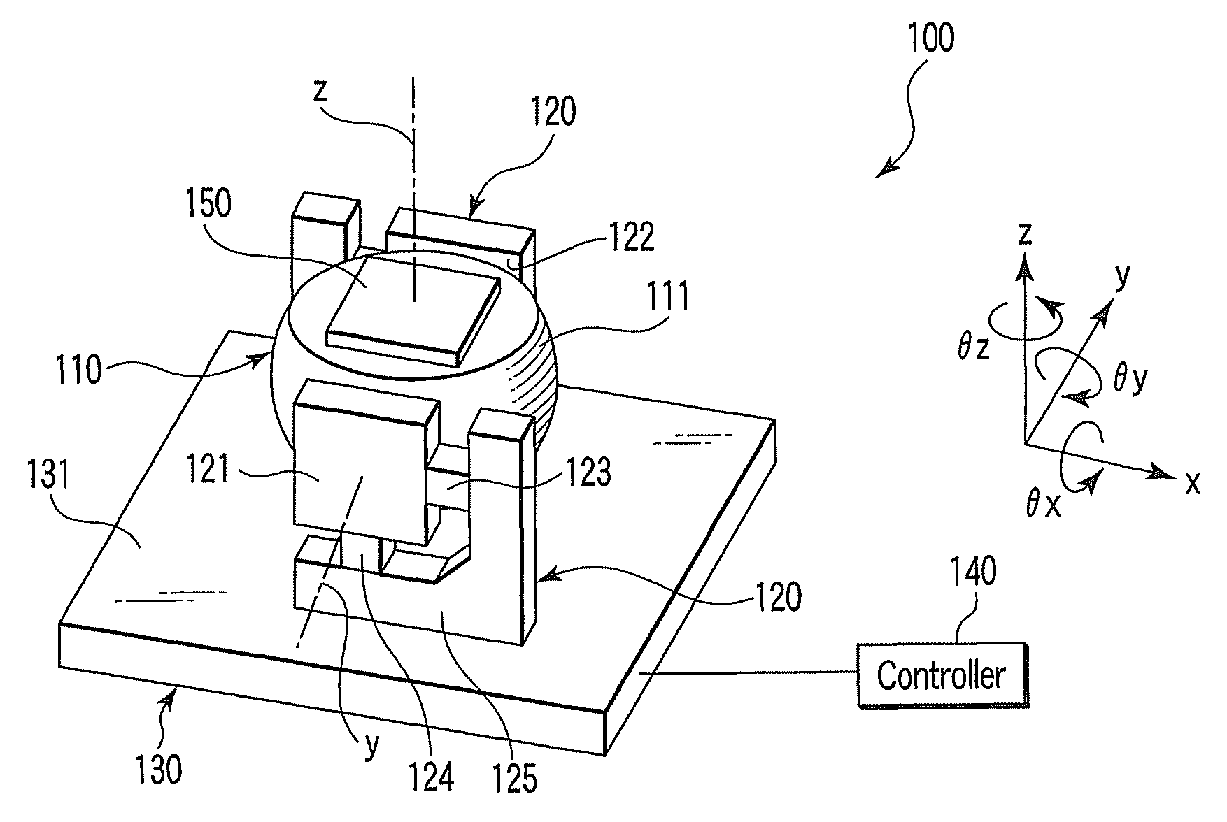
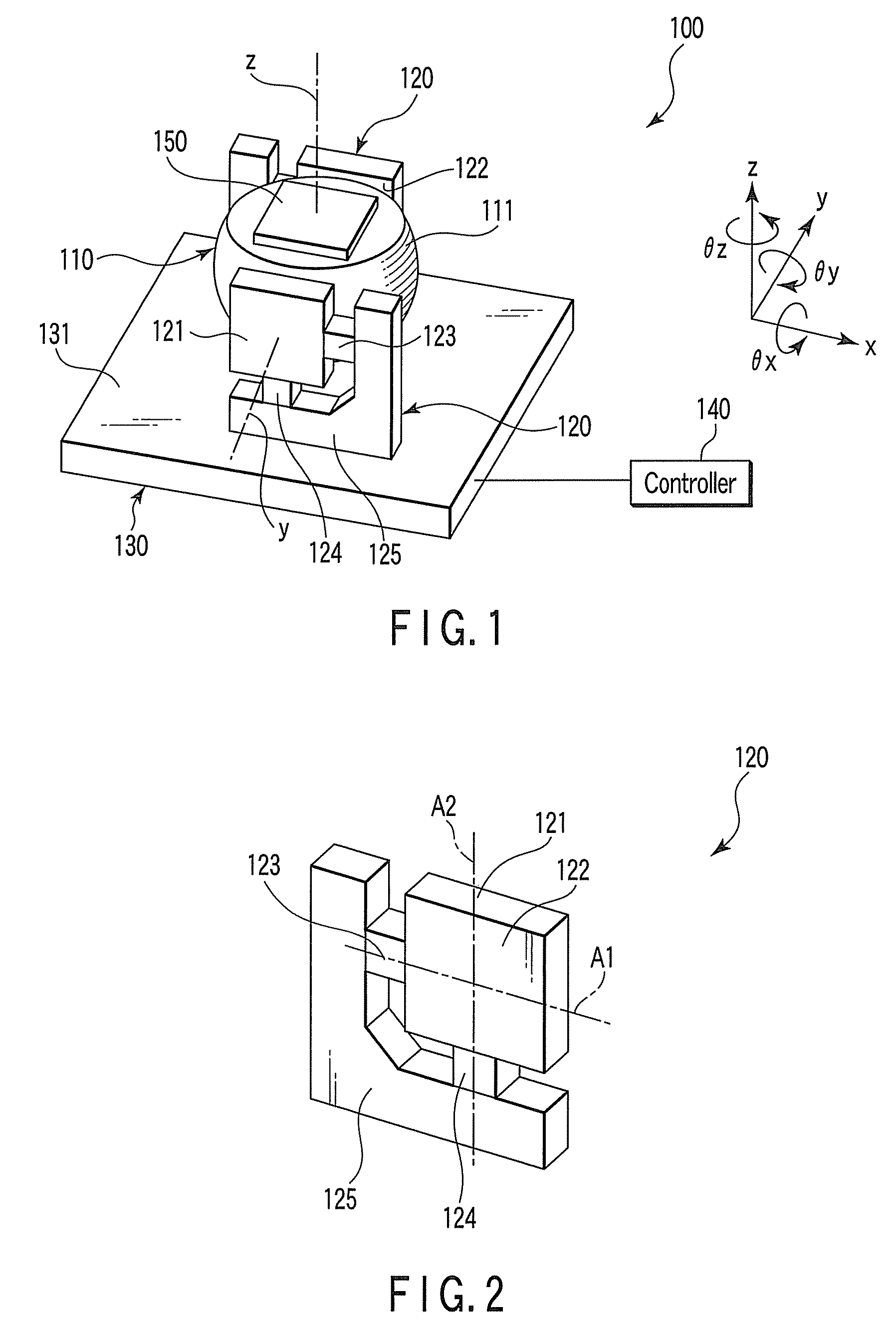
[0039]The arrangement of a driving mechanism according to this embodiment will be described with reference to FIGS. 1 and 2.

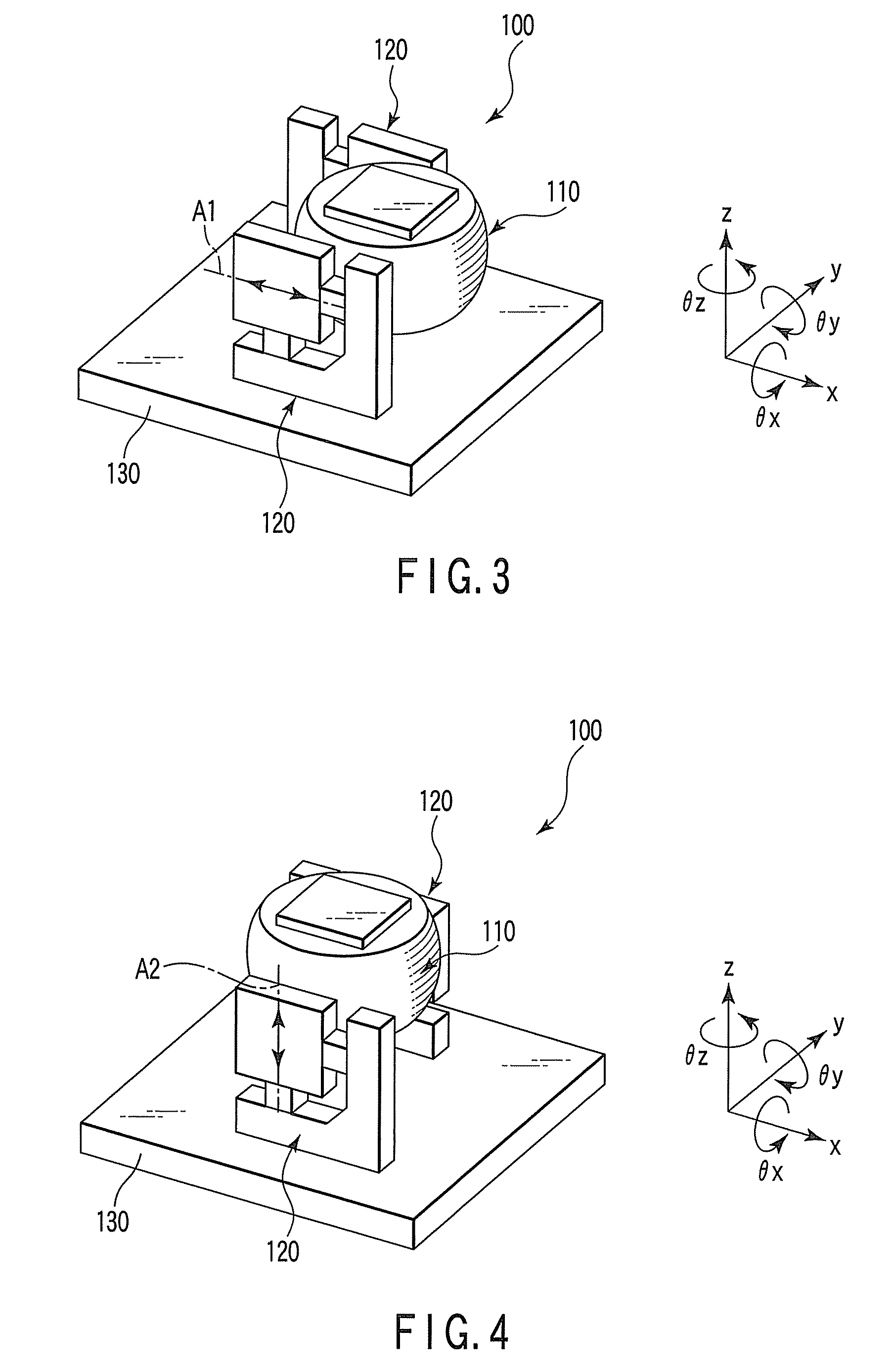
[0040]As shown in FIG. 1, a driving mechanism 100 of this embodiment includes a driven member 110 partially having a spherical surface 111, two piezoelectric units 120 that support the driving mechanism 100 between them and drive it, a base 130 that holds the piezoelectric units 120, and a controller 140 that controls the piezoelectric units 120.

[0041]As shown in FIG. 2, each of the piezoelectric units 120 includes a driving portion 121 having a flat surface 122 in contact with the spherical surface 111 of the driven member 110, a first piezoelectric element 123 that linearly moves the driving portion 121 along a first axis A1 parallel to the flat surface 122, a second piezoelectric element 124 that linearly moves the driving portion 121 along a second axis A2 parallel to the flat surface 122 and perpendicular to the axis A1, and a support member 125 that suppo...

second embodiment

[0051]The second embodiment will be described with reference to FIG. 7. The same reference numerals as in FIG. 7 denote the same members in the first embodiment, and a detailed description thereof will be omitted.

[0052]As shown in FIG. 7, a driving mechanism 200 of this embodiment includes a driven member 110 partially having a spherical surface 111, three piezoelectric units 120 that support the driven member 110 between them and drive the driven member 110, a base 230 that holds the piezoelectric units 120, and a controller 240 that controls the piezoelectric units. The three piezoelectric units 120 are arranged so that driving portions 121 are arranged at equal intervals to surround the driven member 110. Support members 125 are fixed on the base 230 so that the driving portions 121 are located on a circumference slightly smaller than the great circle of the spherical surface of the driven member 110. The great circle is a circle on the cut surface obtained by cutting the spheric...

third embodiment

[0059]The arrangement of a driving mechanism according to the third embodiment will be described with reference to FIG. 8. The same reference numerals as in FIG. 8 denote the same members in the first embodiment, and a detailed description thereof will be omitted.

[0060]As shown in FIG. 8, a driving mechanism 300 according to this embodiment includes a driven member 110 partially having a spherical surface 111, four piezoelectric units 120 that support the driven member 110 between them and drive the driven member 110, a base 330 that holds the four piezoelectric units 120, and a controller 340 that controls the piezoelectric units.

[0061]In the following description, the four piezoelectric units are discriminated by assigning them with reference numerals 120a, 120b, 120c, and 120d. In addition, an xyz orthogonal coordinate system and the θx-, θy-, and θz-axes are set in the same manner as in the first embodiment. That is, the xyz orthogonal coordinate system is set so that the x-and ...


PUM


Abstract

A driving mechanism includes a driven member partially having a spherical surface, piezoelectric units that support the driven member between them and drive the driven member, and a base that holds the piezoelectric units. Each of the piezoelectric units includes a driving portion having a flat surface in contact with the spherical surface of the driven member, a first piezoelectric element that moves the driving portion along a first axis parallel to the flat surface, a second piezoelectric element that moves the driving portion along a second axis that is parallel to the flat surface and intersects the first axis, and a support member that supports the driving portion through the first and second piezoelectric elements.

Description

CROSS-REFERENCE TO RELATED APPLICATIONS[0001]This application is based upon and claims the benefit of priority from prior Japanese Patent Application No. 2007-084276, filed Mar. 28, 2007, the entire contents of which are incorporated herein by reference.BACKGROUND OF THE INVENTION[0002]1. Field of the Invention[0003]The present invention relates to a driving mechanism that drives a driven member by using piezoelectric elements.[0004]2. Description of the Related Art[0005]In the field of multi-degree-of-freedom control systems represented by six-degree-of-freedom positioning mechanisms used for visual line change control on surveillance cameras and the like and for semiconductor manufacturing apparatuses, a driving mechanism or motor system having an arrangement in which single-axis driving motors are connected in series and stacked on each other has been widely used. Recently, in particular, attention has been paid to research and development of a mechanism that can perform multi-de...

Claims


Application Information

Patent Timeline
Patent Type & Authority Patents(United States)
IPC IPC(8): G03B17/00H02N2/02
CPCG03B17/00G03B35/10H02N2/0025H02N2/103H02N2/108G03H1/265G03H1/28H04N5/23287H04N23/687
Inventor TAKAHASHI, HIROSHI
Owner KK TOSHIBA
Why Eureka
Try Eureka