Laboratory instrument with a protected working compartment

a working compartment and laboratory equipment technology, applied in the direction of instruments, wing accessories, hinges, etc., can solve the problems of inability to determine the exact weight of the weighing object, the weighing object is often unstable, and the weighing object is difficult to access, etc., to achieve excellent access to the working compartment, reduce the height dimension, and reduce the amount of free space required above the working compartment.

Active Publication Date: 2010-11-16
METTLER TOLEDO GMBH
View PDF22 Cites 11 Cited by
  • Summary
  • Abstract
  • Description
  • Claims
  • Application Information

AI Technical Summary

Benefits of technology

[0013]By having access from three sides, working in the working compartment is made considerably easier. Access from the side in this context refers only to the accessibility of the working compartment by way of the approaches laid open by the sidewalls and the front wall. The terms “top, bottom, front, rear, and side” as used farther below refer to the spatial dimensions of a laboratory instrument set up in a normal operating position.
[0016]The front wall with its ability to slide and swivel relative to the housing, with the swivel angle being tied to the amount of linear sliding displacement as a result of the guiding device, provides in combination with the slidable sidewalls the ideal solution to meet the foregoing requirements. First of all, access to the working compartment is excellent, as the front wall in its open position does not cover up any of the sidewalls and the working compartment can therefore always be accessed from the side. Second, the combined sliding and swiveling movement essentially slices the air, and the influence of air turbulence which would be caused by a pure swiveling movement is minimized. Third, with the simultaneous swiveling of the front wall the free space that is required above the working compartment is significantly reduced in comparison to the space required with a purely linear sliding movement of the front wall, which in turn leads to significantly reduced height dimensions for example in fume hoods or glove boxes.
[0017]A configuration where the rear wall and the floor of the working compartment are wall portions of the housing is conducive not only to a very compact design of the laboratory instrument but also to a very stable, deformation-resistant working compartment.
[0021]However, the coordination which ties the swivel movement to the linear sliding movement of the front wall does not necessarily have to be accomplished by mechanical means. If mechanically separate drive sources are provided for the swivel movement as well as for the linear sliding movement of the front wall, the kinematic profile of the two movements can be freely selected and, if compatible with the way in which these drive sources are controlled, it can also be changed in any desired way. To perform such tasks, drive mechanisms with a piezoelectric element are particularly well suited. They have the advantage that little space is required to accommodate the drive source. The drive mechanism is small and compact and can therefore be mounted in any desired location. As a further advantage, the build-up of electrostatic charges on the drive mechanism or any of its parts is avoided. The drive mechanism is further free of any magnetic or magnetizable parts which could interfere with the operation of a weighing cell that is based on the principle of electromagnetic force compensation.

Problems solved by technology

Consequently, even the smallest extraneous influences affecting the weighing object or the load receiver can cause an error in the weighing result.
The extraneous influence factors are rarely stable, and this can lead to situations where the exact weight of the weighing object cannot be determined.
The reason why this is not possible with state-of-the-art designs is that laboratory instruments with a working compartment have to meet a number of different requirements.
However, the coordination which ties the swivel movement to the linear sliding movement of the front wall does not necessarily have to be accomplished by mechanical means.
The guide track or guide groove is laid out in such a way that the front wall in the open position does not cover up a sidewall and thus does not prevent the sidewall from being opened.

Method used


Image

  • Laboratory instrument with a protected working compartment
  • Laboratory instrument with a protected working compartment
  • Laboratory instrument with a protected working compartment

Examples


first embodiment

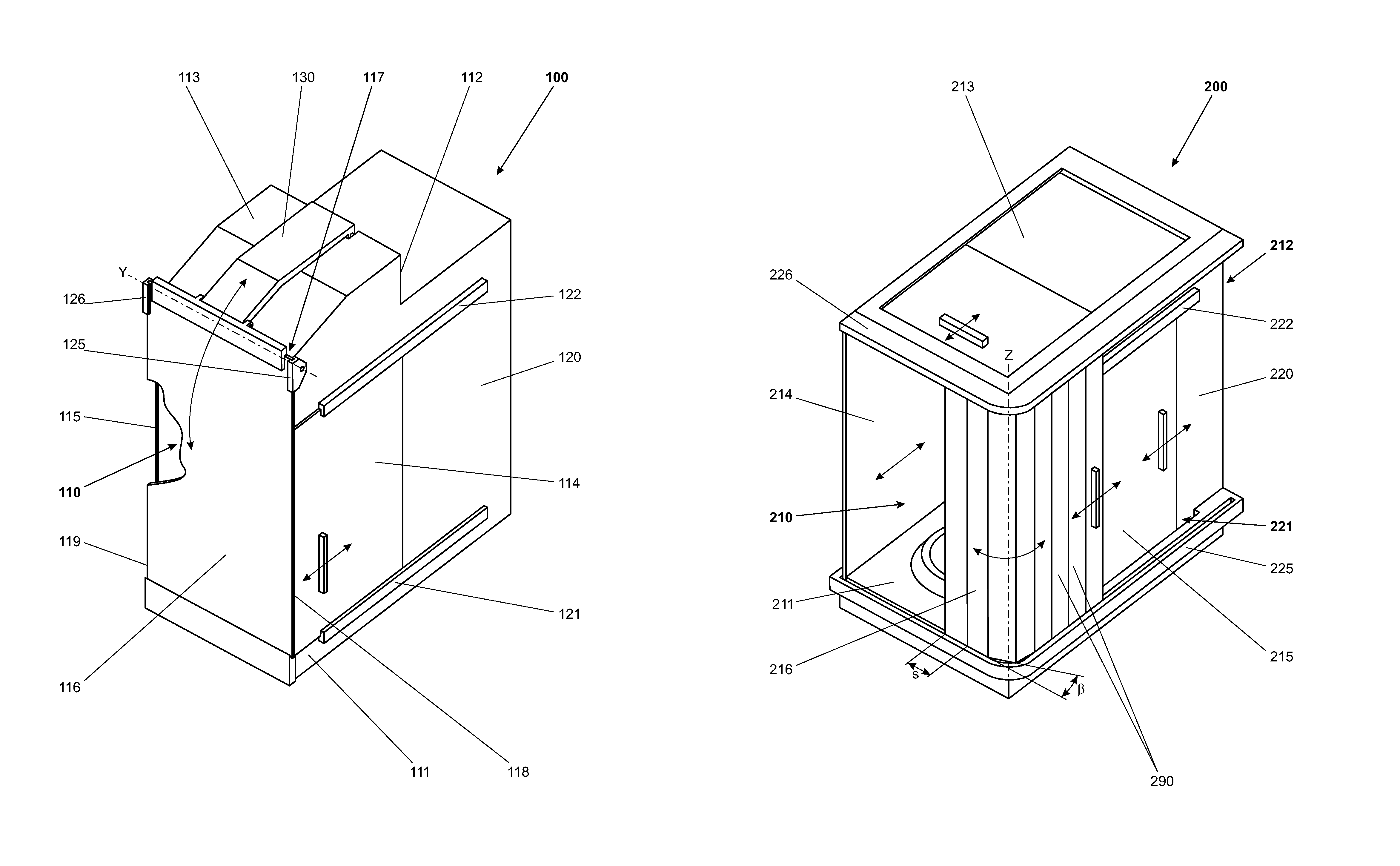
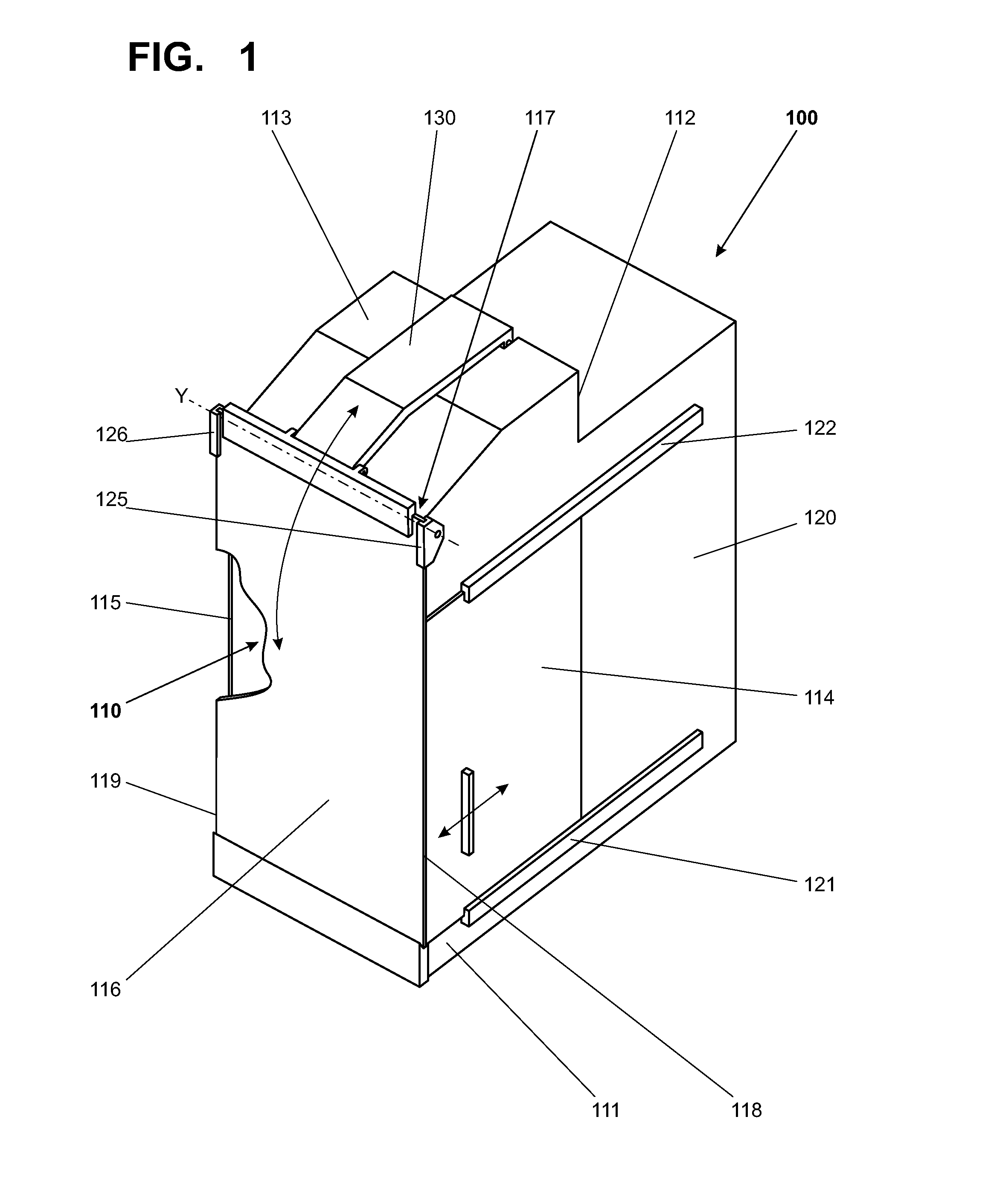
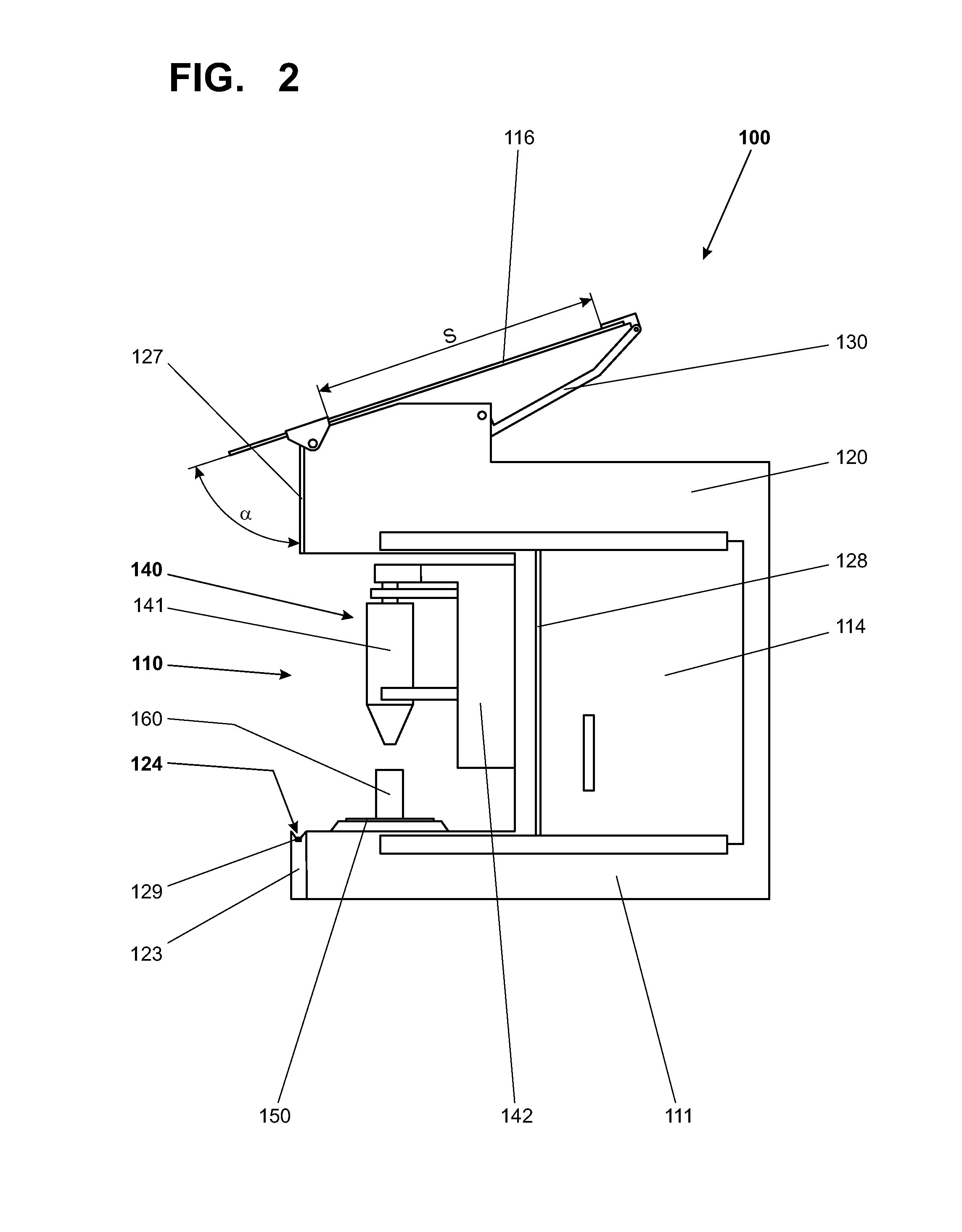
[0038]FIG. 1 shows a three-dimensional view of a laboratory instrument 100 in a first embodiment, with a working compartment 110 shown in the closed state and with a housing 120 adjoining the weighing compartment. The floor 111, the rear wall 112 and the top cover 113 of the working compartment 110 are configured as parts of the housing 120. The working compartment 110 is delimited at the sides by two sidewalls 114, 115 which are guided by tracks 121, 122 and thereby constrained so that they can only slide to the back in a linear movement. The working compartment 110 is delimited towards the front by a plate-shaped rigid front wall 116.

[0039]The front wall 116 is constrained by two linear sliding guides 125, 126 which are pivotally connected to the housing 120 and thus are part of a guiding device for the front wall 116. One of the two linear sliding guides is arranged in each corner area of the front edge 117 of the top cover 113 with the ability to pivot about a horizontal swivel ...

second embodiment

[0048]FIG. 3 shows a laboratory instrument 200 in three-dimensional view in a second embodiment which likewise has a housing 220 and a working compartment 210. The floor 211, the rear wall 212 and the top cover 213 of the working compartment 210 are configured as parts of the housing. The working compartment 210 is delimited on the sides by two sidewalls 214, 215 which are guided in tracks 221, 222 and can be pushed to the back in a straight-line movement. The working compartment 210 is further delimited towards the front by a front wall 216 which has a multi-part configuration. It consists essentially of a plurality of lamellar sections 290 which are articulately connected to each other. The front wall 216 is guided by guide tracks 225, 226 arranged, respectively, in the floor 211 and the top cover 213 and serving as guiding devices. These guide tracks 225, 226 extend along the front edge and one side of the laboratory instrument 200. These tracks have essentially one guide groove ...


PUM


Abstract

A laboratory instrument with a housing containing a weighing cell has a working compartment that is connected to the housing. The working compartment has a floor, a top cover, a rear wall, a front wall and two sidewalls. Arranged in the working compartment is a load receiver which is connected to the weighing cell. Also connected to the housing is at least one guiding device which serves to guide a linear movement and simultaneous swivel movement of individual portions of the front wall or the entire front wall.

Description

CROSS-REFERENCE TO RELATED APPLICATIONS[0001]This application is a continuation under 35 USC §120 of PCT / EP2008 / 063266, filed 3 Oct. 2008, which is in turn entitled to benefit of a right of priority under 35 USC §119 from European patent application 07 12 1016.5, which was filed 19 Nov. 2007. The content of each of the applications is incorporated by reference as if fully recited herein.TECHNICAL FIELD[0002]The disclosed embodiments relate to a laboratory instrument with a working compartment, a housing which contains a weighing cell, and a load receiver which is arranged in the working compartment and connected to the weighing cell, further with a floor, a top cover, a rear wall, a front wall and two sidewalls, which delimit the working compartment against the surrounding space of the laboratory instrument.BACKGROUND OF THE ART[0003]Laboratory instruments of this kind serve for example as analytical balances in many fields of industry, particularly in laboratories of research- and ...

Claims


Application Information

Patent Timeline
Patent Type & Authority Patents(United States)
IPC IPC(8): G01G21/00G01G21/28
CPCG01G21/286E05D1/02E05D1/04E05D15/408E05Y2900/20E05Y2900/538E06B3/5045E05Y2900/60
Inventor ZEISS, SIEGFRIEDNUFER, BRUNO
Owner METTLER TOLEDO GMBH
Why Eureka
Try Eureka