
Thermal runaway protection system for a battery charger

a protection system and battery charger technology, applied in the direction of battery overheat protection, safety/protection circuit, electrochemical generator, etc., can solve the problems of thermal runaway, electrolyte to get even hotter, damage to the battery as well as personal injury

Active Publication Date: 2010-11-16
SCHUMACHER ELECTRIC CORP
View PDF10 Cites 18 Cited by
  • Summary
  • Abstract
  • Description
  • Claims
  • Application Information

AI Technical Summary

Benefits of technology

The present invention is about a protection system for battery chargers that detects when a battery is overheating during charging. This system does not require external temperature sensors or user action. It uses electrical sensors that monitor the charging characteristics of the battery. If the charging characteristics deviate from normal, the system assumes there may be a thermal runaway condition and takes protective measures, such as stopping the charging of the battery. This system treats even small abnormalities as potential problems that require corrective action.

Problems solved by technology

Thermal runaway can cause overheating of a battery during charging which can result in damage to the battery as well as personal injury.
More particularly, thermal runaway occurs when the electrolyte in the battery gets hot.
The increased charging current causes the electrolyte to get even hotter. resulting in the even more charging current to be drawn by the battery placing the battery in a thermal runaway condition.
The risk of a battery experiencing a thermal runaway condition is increased during relatively high ambient temperature conditions.
For example, in flooded electrolyte batteries, such as lead acid batteries, a thermal runaway condition can cause the electrolyte to boil off; thereby disabling the battery.
In sealed batteries, a thermal runaway condition can cause expansion of the electrolyte and an explosion of the battery and possibly personal injury.
Although such battery chargers which rely on external temperature sensors to detect and protect against a thermal runaway condition, there are several problems with such systems.
In particular, many conventional batteries are not known to be provided with temperature sensors.
There are several known problems with such hardware solutions.
However, the service technicians may not always connect the temperature sensors to the battery surface or battery terminals.
Without the battery temperature, the battery charging system is unable to detect a thermal runaway condition.
Moreover, the electrical conductors attached to the temperature sensors may eventually break off after repeated use.
Such a solution essentially renders the battery charger unusable until the broken wire is repaired.
Moreover, if the thermistor used to sense battery temperature is damaged or becomes disconnected from the electrical conductor or becomes misplaced, the battery charger is rendered inoperable
Although relative high ambient temperatures can result in a thermal runaway condition, the system does not take into account the temperature of the battery and thus is a relatively crude and inaccurate method for detecting a thermal runaway protection.
Moreover, the technicians may not always remember to set the manual ambient temperature switch.

Method used


Image

  • Thermal runaway protection system for a battery charger
  • Thermal runaway protection system for a battery charger
  • Thermal runaway protection system for a battery charger

Examples


Embodiment Construction

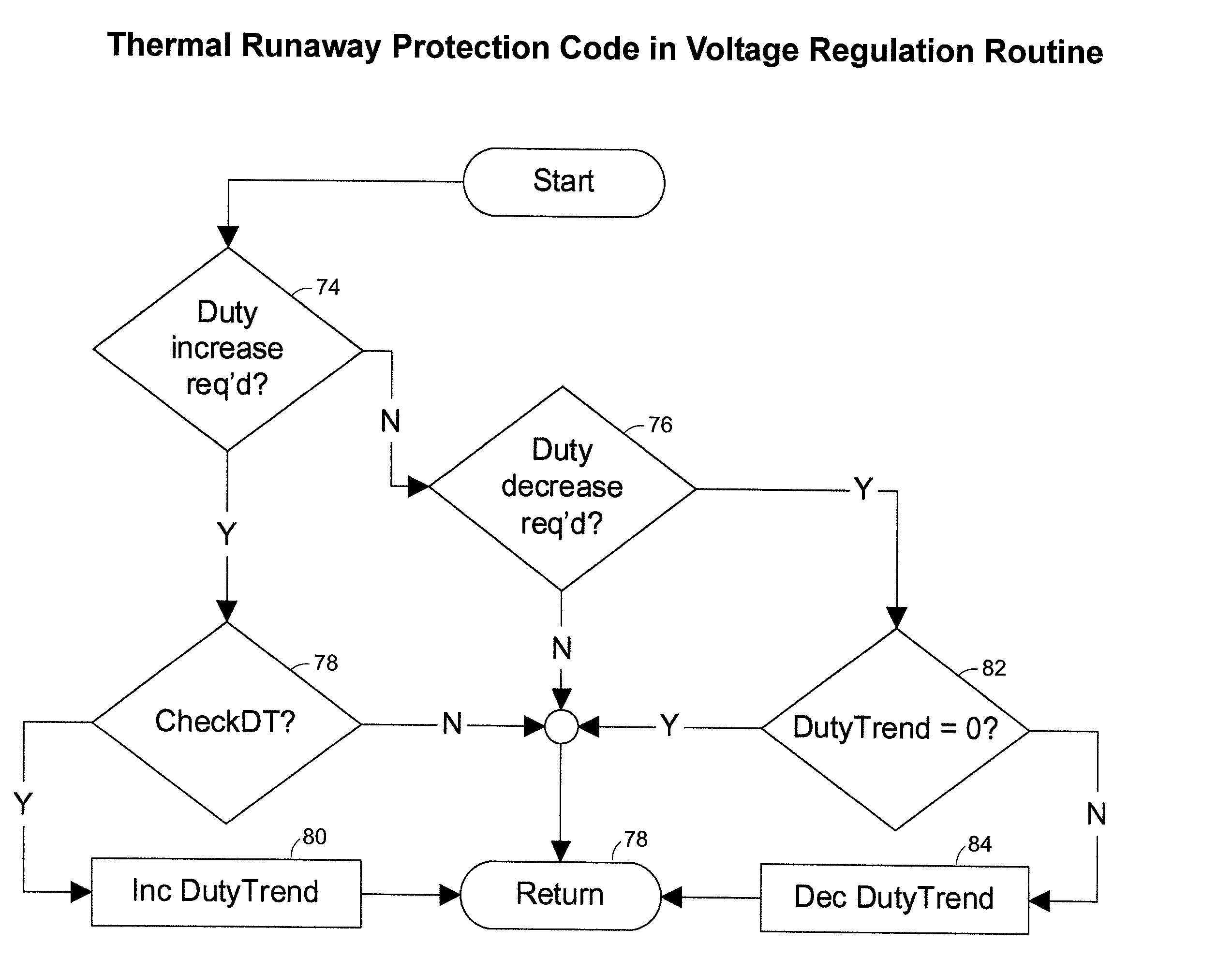
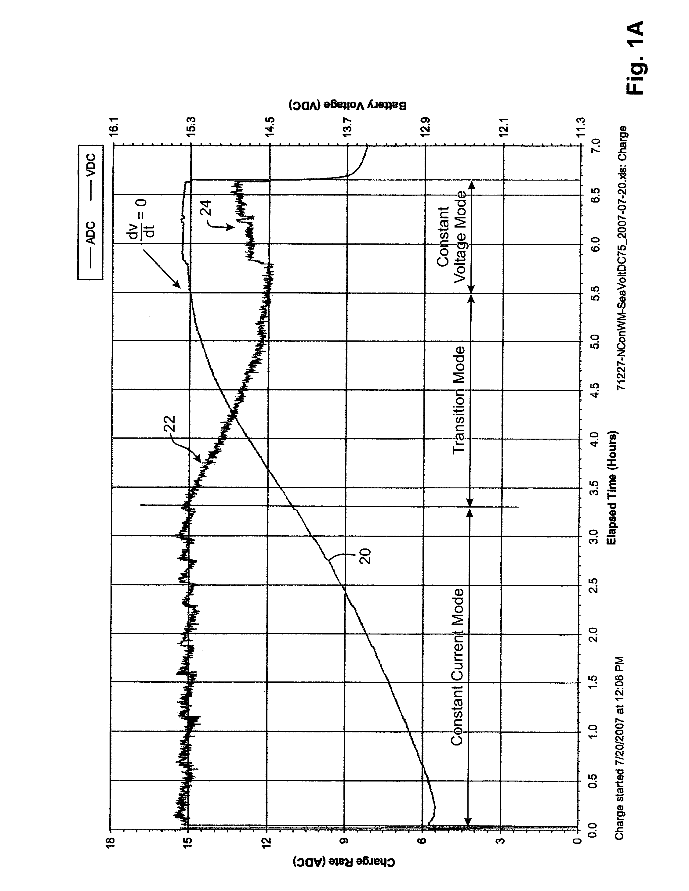
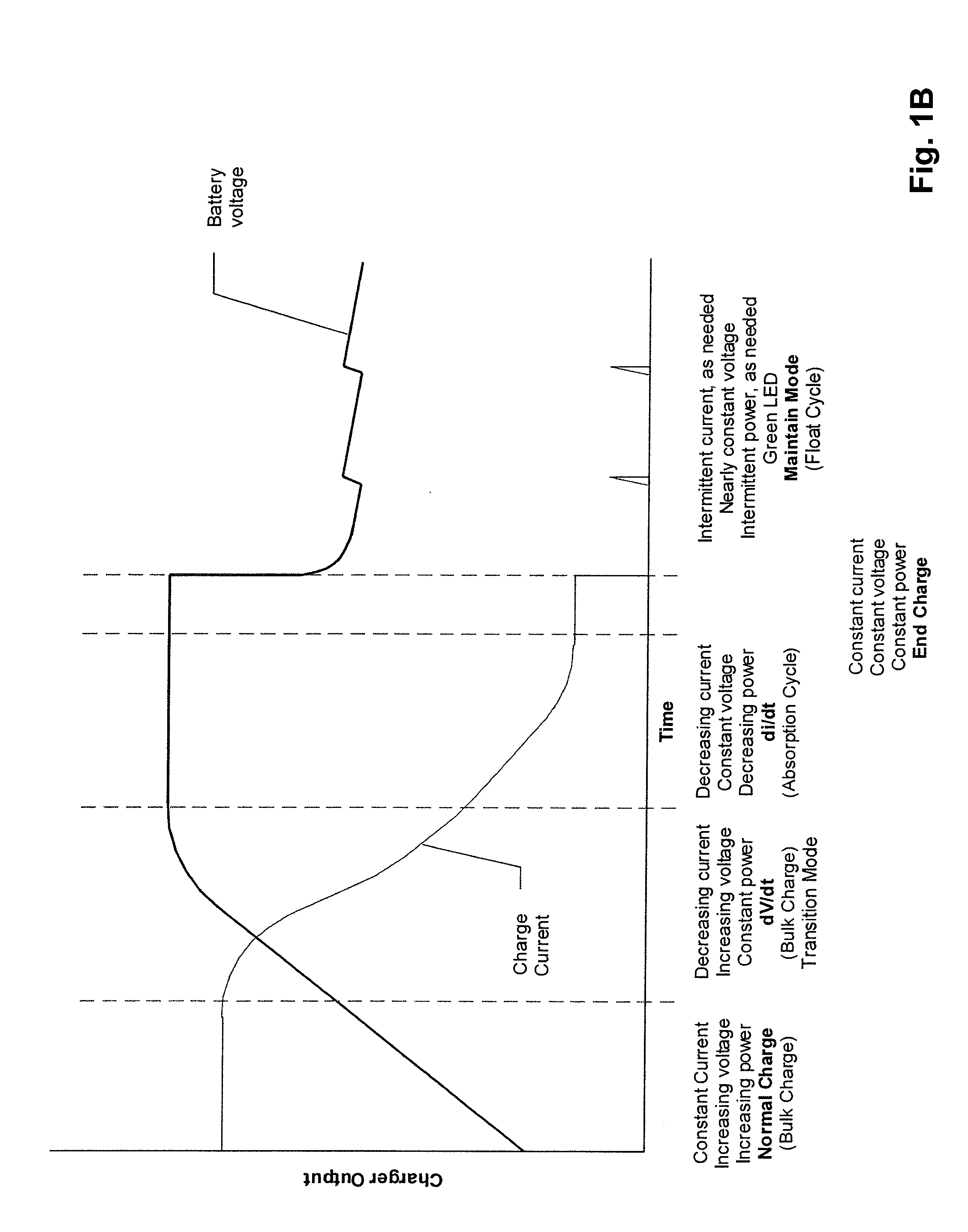
[0025]The present invention relates to a protection system for a battery charger that utilizes software to detect a thermal runaway condition, thereby eliminating the need for external temperature sensors and which does not rely on actions by the technician or user. Briefly, the protection system includes one or more electrical sensors for sensing one or more electrical parameters and determining a thermal runaway condition based upon the trend of the electrical charging parameters. In general, the system monitors the charging characteristics of a battery during a normal charging cycle. If the charging characteristics deviate from a normal charging cycle by a significant amount as determined by software, the system assumes a thermal runaway condition. For example, in one embodiment of the invention, the voltage and current is monitored during an initial phase of the charging cycle in which the charging current is held constant or controlled and the voltage is monitored.

[0026]During ...


PUM


Abstract

A protection system and method for a battery charger is disclosed for detecting a thermal runaway condition in a battery during charging in order to protect the battery when such a thermal runaway condition has been detected. The protection system in accordance with the present invention does not require external temperature sensors nor does it rely on actions by the technician or user. Briefly, the protection system includes one or more electrical sensors normally provided with conventional battery chargers for sensing one or more electrical parameters during charging and providing an indication of a possible thermal runaway condition based upon the trend of the electrical charging parameters. In general, the protection system monitors the charging characteristics of a battery for a complete or partial charging cycle. If the charging characteristics deviate from a normal or otherwise indicate an anomaly, as determined by software, the system assumes there may be a thermal runaway condition and executes a protection measure, such as terminating charging of the battery. Even though the anomaly may not be the result of a thermal runaway condition, the protection system in accordance with the present invention treats the anomaly as an indication of a thermal runaway condition even though some other problem is the reason for the anomaly. For example, when the anomaly is the result of a bad cell, battery charging is terminated to prevent a thermal runaway condition and not because a thermal runaway condition is detected.

Description

BACKGROUND OF THE INVENTION[0001]1. Field of the Invention[0002]The present invention relates to a protection system for use with a battery charger and more particularly to a protection system for a battery charger for detecting a thermal runaway condition during charging of a battery and protecting the battery when such a thermal runaway condition is detected.[0003]2. Description of the Prior Art[0004]Various battery chargers are known in the art. Some known battery chargers include protection against a thermal runaway condition. Thermal runaway can cause overheating of a battery during charging which can result in damage to the battery as well as personal injury. Thermal runaway occurs as a result of heating of the electrical conductors in the battery during charging. More particularly, thermal runaway occurs when the electrolyte in the battery gets hot. When the electrolyte gets hot, heat is transferred from the electrolyte to the electrical conductors within the battery causing ...

Claims


Application Information

Patent Timeline
Patent Type & Authority Patents(United States)
IPC IPC(8): H02J7/04H02J7/16
CPCH01M10/443H01M10/486H02J7/0029Y02E60/10H02J7/00309
Inventor JOHNSON, THOMAS F.WHITING, JOHN S.
Owner SCHUMACHER ELECTRIC CORP
Learn More