Optical disk recording and reproducing device

a technology of optical disk and recording device, which is applied in the direction of digital signal error detection/correction, electronic editing digitised analogue information signals, instruments, etc., can solve the problems of inability to grasp the deterioration of the optical disk on the time scale, the inability of users to detect the jitter value of the read signal, and the inability to perceive the deterioration of digital data recorded on the optical disk. , to achieve the effect of preventing the loss of importan

Inactive Publication Date: 2010-11-16
FUNAI ELECTRIC CO LTD
View PDF6 Cites 2 Cited by
  • Summary
  • Abstract
  • Description
  • Claims
  • Application Information

AI Technical Summary

Benefits of technology

[0009]An object of the present invention is to provide an optical disk recording and reproducing device that can grasp a deteriorated situation of an optical disk on the time scale so that a user can prepare or take measures for the backup in advance, and that the user can back up data recorded on a writable optical disk before the data become unable to be read due to a scratch on the recording surface or alteration of dye of the optical disk.
[0011]According to this structure, a deteriorated situation of an optical disk on the time scale can be grasped so that the user can prepare or take measures for the backup in advance.
[0012]In addition, before the data recorded on the optical disk become unable to be read due to a scratch on the recording surface or alteration of dye of the optical disk, user can be informed of the deterioration. Thus, the user can back up the data recorded on the optical disk quickly, so that a data loss of an important record can be avoided.
[0016]In another preferred embodiment of the present invention, the system controller further includes a backup determining portion for determining whether or not the backup of the recorded data can be performed on the same optical disk by detecting a free space and a designated area for rewriting on the optical disk, a backup controlling portion for controlling the backup of the recorded data on the same optical disk in the free space or the designated area for rewriting of the optical disk when it is determined that the backup of the recorded data can be performed on the same optical disk, and a backup instructing portion for instructing to perform the backup of the recorded data on another optical disk when it is determined that the backup of the recorded data cannot be performed on the same optical disk. According to this structure, if there is a free space or a designated area for rewriting on the optical disk, the user can back up the recorded data on the same optical disk. If the backup cannot be performed on the same optical disk, an instruction to perform the backup on another optical disk can be given. Thus, the user can use the optical disk effectively when the backup is performed.
[0018]In addition, since the user can notice a deterioration of the optical disk before the data become unable to be read due to a scratch on the recording surface or alteration of dye of the optical disk, the user can back up data recorded on the optical disk promptly so that a loss of important recorded data can be prevented.
[0019]In addition, recorded data can be backed up on the same optical disk if there is a free space or a designated area for rewriting on the optical disk, while it is instructed to perform the backup on another optical disk if the backup cannot be performed on the same optical disk. Thus, the user can use the optical disk effectively when the backup is performed.

Problems solved by technology

Although deterioration of analog data recorded on a magnetic tape like a video cassette tape can be sensed by a user when the reproduced image is deteriorated due to the deterioration of the magnetic tape, it is difficult for a user to perceive deterioration of digital data recorded on an optical disk such as a DVD even if it has a scratch on the recording surface or alteration of dye, because of the error correcting process.
However, it does not detect a jitter value of the read signal from the optical pickup.
Therefore, the deteriorated situation of the optical disk on the time scale cannot be grasped.
In other words, it is difficult to know whether the deterioration has been generated gradually or abruptly, so the user cannot prepare or take measures for the backup in advance.

Method used


Image

  • Optical disk recording and reproducing device
  • Optical disk recording and reproducing device
  • Optical disk recording and reproducing device

Examples


Embodiment Construction

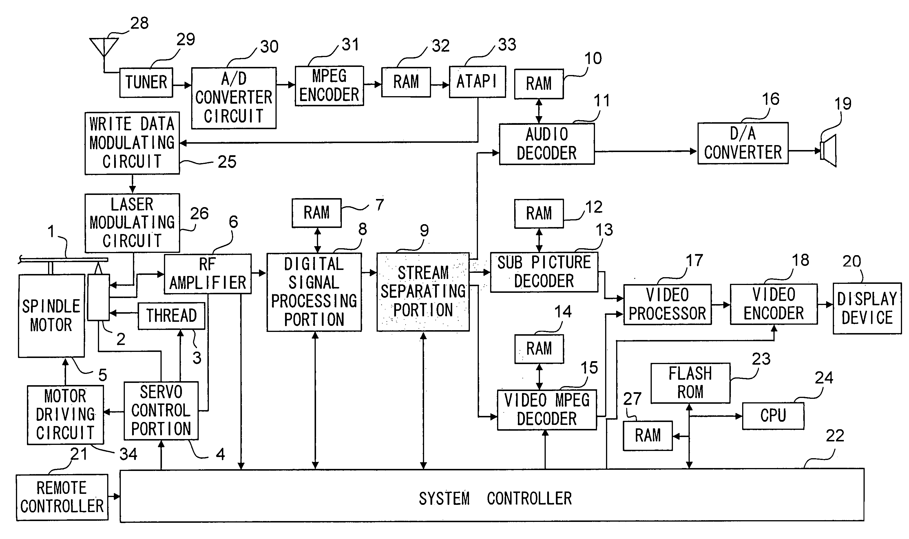
[0025]Now an embodiment of the present invention will be described with reference to the attached drawings. FIG. 1 is a block diagram showing a structure of an optical disk recording and reproducing device according to an embodiment of the present invention.

[0026]This optical disk recording and reproducing device is equipped with a system controller 22 for controlling a whole device, a spindle motor 5 for rotating an optical disk 1, an optical pickup 2 for writing and reading information on the optical disk 1 optically, a thread 3 for moving the optical pickup 2 in the radial direction of the optical disk 1, and a servo control portion 4 for driving the spindle motor 5 and the thread 3 via a motor driving circuit 34 and moving an objective lens (not shown) embedded in the optical pickup 2 so that a focus position of a laser beam is moved with respect to a recording surface of the optical disk 1 in the vertical direction and in the horizontal direction in accordance with an instructi...


PUM

PropertyMeasurementUnit
areaaaaaaaaaaa
timeaaaaaaaaaa
structureaaaaaaaaaa

Abstract

A system controller of an optical disk recording and reproducing device makes a display portion display a precaution message for recommending a user to back up data recorded on the optical disk when it is determined that one or more values including a jitter value, a variation quantity of the jitter value, a block error rate and a block error rate at a particular position have exceeded precaution reference values. In addition, it makes a display portion display an urgent message for instructing a user to back up data recorded on the optical disk quickly when it is determined that one or more of the values have exceeded limit reference values.

Description

[0001]This application is based on Japanese Patent Application. No. 2005-338643 filed on Nov. 24, 2005, the contents of which are hereby incorporated by reference.BACKGROUND OF THE INVENTION[0002]1. Field of the Invention[0003]The present invention relates to an optical disk recording and reproducing device for recording and reproducing information on an optical disk. In particular, the present invention relates to an optical disk recording and reproducing device having a function of instructing backup of the optical disk before data recorded on it becomes unable to be read due to a scratch on its recording surface, alteration of dye or the like.[0004]2. Description of Related Art[0005]Recently, a digital versatile disk (DVD) that is an optical disk capable of recording a large quantity of video and audio data such as a movie has become commonplace. There are several types of the DVD includes a DVD-ROM that stores information recorded on a manufacture's side and cannot be rewritten ...

Claims


Application Information

Patent Timeline
Patent Type & Authority Patents(United States)
IPC IPC(8): G11B7/00
CPCG11B19/04G11B20/1816G11B27/034G11B27/36G11B2020/1869G11B2220/2537
Inventor NAKAYAMA, SHUHEI
Owner FUNAI ELECTRIC CO LTD
Why Eureka
Try Eureka