Information Recording Drive, Information Recording Media and Detection Method of Deterioration Situation of Information Recording Media

a technology of information recording media and monitor marks, which is applied in the direction of recording devices, carrier indicating arrangements, instruments, etc., can solve the problems of monitor marks deteriorating before the marks as the record data is deteriorating, user cannot know whether recorded data has been deteriorated, and user cannot read data, etc., to achieve the effect of lowering the quality of data

Inactive Publication Date: 2007-12-06
HITACHI LTD
View PDF1 Cites 4 Cited by
  • Summary
  • Abstract
  • Description
  • Claims
  • Application Information

AI Technical Summary

Benefits of technology

[0009]According to the present invention, monitor marks indicating a deterioration situation of record data are recorded in an optical disk. A user can know a deterioration situation by looking at the monitor marks. It is therefore possible for the user to make countermeasures for deterioration of record data, e.g. to back up the record data.
[0011]If the monitor marks are recorded under a recording condition providing easier deterioration than the marks recorded for data recording, the monitor marks are deteriorated before the marks as the record data are deteriorated. It is therefore possible to know a lowered quality of record data. Since the deterioration situation can be known before the record marks are deteriorated (before the quality of record data lowers), a user can perform a countermeasure such as backup while the record data can be accessed.
[0014]The information recording medium is recorded with data in a data recording layer through energy radiation, e.g., by changing an arrangement of atoms in the data recording layer, and is recorded with monitor marks to monitor the deterioration situation of the data recording layer. It is therefore possible to detect the deterioration situation of the information recording medium by utilizing a change in the reflectivity of the monitor marks to be caused by deterioration. A user can know the deterioration situation of record data, i.e., record marks, from the detection results.
[0016]According to the present invention, it is possible to know the deterioration situation (a lowered quality of data) of record marks recorded in an optical disk.

Problems solved by technology

With these conventional methods, a user cannot know whether recorded data has been deteriorated so that the user cannot read data in some cases.
If the monitor marks are recorded under a recording condition providing easier deterioration than the marks recorded for data recording, the monitor marks are deteriorated before the marks as the record data are deteriorated.

Method used


Image

  • Information Recording Drive, Information Recording Media and Detection Method of Deterioration Situation of Information Recording Media
  • Information Recording Drive, Information Recording Media and Detection Method of Deterioration Situation of Information Recording Media
  • Information Recording Drive, Information Recording Media and Detection Method of Deterioration Situation of Information Recording Media

Examples


first embodiment

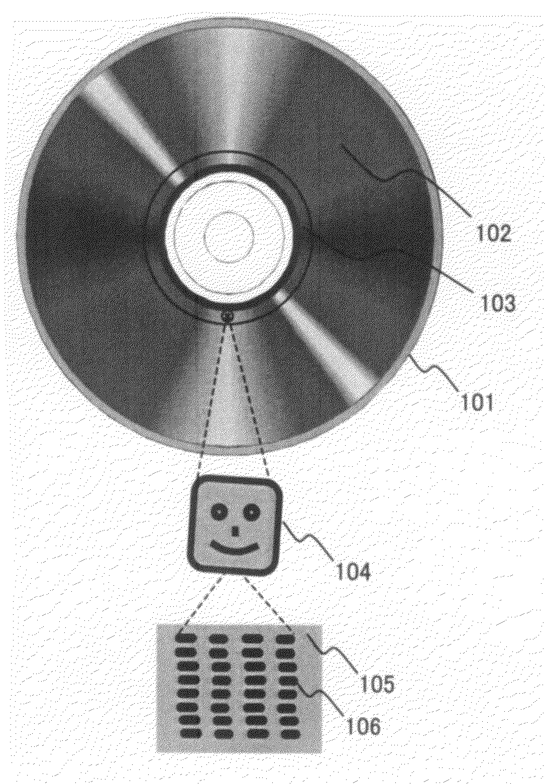
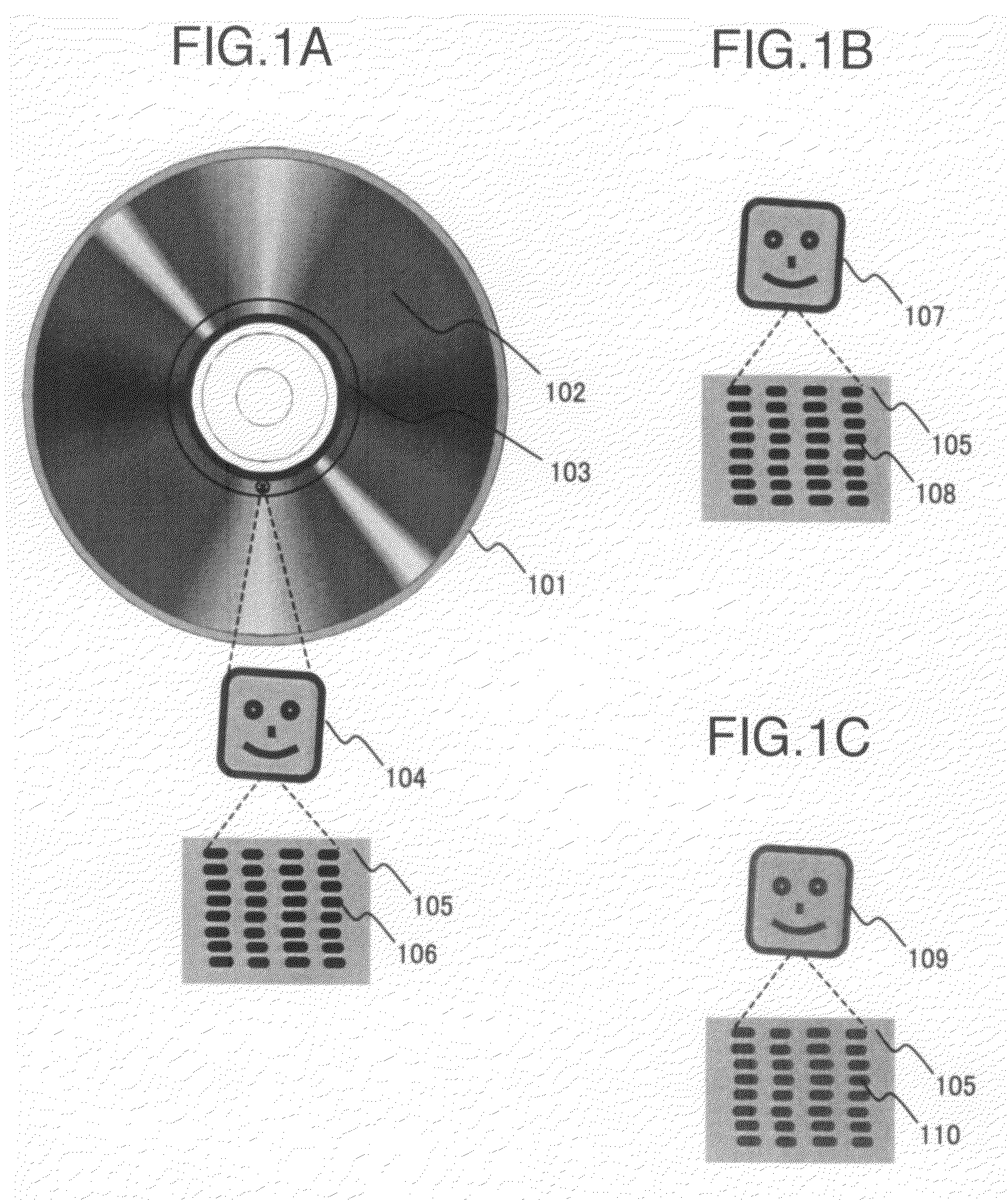
[0045]FIGS. 1A to 1C are schematic diagrams showing an example of an optical disk of the present invention. The optical disk 101 has a region 102 where data is recorded and a region 103 where monitor marks are recorded for grasping a deterioration situation. A monitor FIG. 104 was recorded while data was recorded or immediately before or after data recording. The monitor FIG. 104 immediately after data recording is made of a set of a number of monitor marks 106 in a space 105. In order to check the deterioration situation of the disk, the disk was left in a vehicle exposed to direct sun rays. The inside of the vehicle was heated to 150° C. at a maximum. FIG. 1B shows a monitor FIG. 107 after three months after the disk was left in the vehicle. The monitor FIG. 107 has a smaller difference of the reflectivity from that of the space 105 and has a smaller contrast. This is because the reflectivity of the monitor marks 108 constituting the monitor FIG. 107 becomes near the reflectivity ...

second embodiment

[0065]The second embodiment of the present invention shows examples that a figure as a set of monitor marks floats or changes its shape.

[0066]A symbol 1201 is constituted of monitor marks 1202 and 1203 written under different recording conditions, and is completely filled with marks written under at least two recording conditions. Immediately after recording, the figure cannot be visually recognized. After the disk is left about three months, as shown by a symbol 1204 of FIG. 12B, a figure “NG” is visible because of a reflectivity difference between the monitor marks 1203 recorded under the recording condition of easy to deteriorate and the monitor marks 1204 recorded under the recording condition of hard to deteriorate. After the disk is left further one year, a FIG. 1207 shown in FIG. 12C is more clearly visible because of a large reflectivity difference between the monitor marks 1203 recorded under the recording condition of easy to deteriorate and the monitor marks 1202 recorded...

third embodiment

[0070]The third embodiment of the present invention shows an example of the optical disk drive for monitoring a deterioration situation.

[0071]FIG. 14 is a schematic block diagram showing an example of an optical disk drive having a function of monitoring a deterioration situation from monitor marks according to the present invention. For the convenience of description, the drive is shown with the optical disk 101 loaded therein. The optical disk 101 is essential for monitoring the deterioration situation. When necessary, the optical disk 101 may be dismounted from or mounted on the optical disk drive.

[0072]The optical disk drive is constituted of: an optical head 504 being movable in a radial direction of the optical disk 101 and equipped with a semiconductor laser 501, a photodetector 502, and an objective lens 503; a motor 505 for driving and rotating the optical disk 101; a laser driver 507 for controlling the semiconductor laser 501 to use it as a monitoring reproduction power; ...


PUM


Abstract

To know whether recorded data has been deteriorated. In an information recording medium recording data in a data recording layer through a change in atom arrangement caused by energy radiation, monitor marks are being recorded in the data recording layer to monitor a deterioration situation. A user can know the deterioration situation of recorded data.

Description

INCORPORATION BY REFERENCE[0001]The present application claims priority from Japanese application JP2006-154170 filed on Jun. 2, 2006, the content of which is hereby incorporated by reference into this application.BACKGROUND OF THE INVENTION[0002]1. Field of the Invention[0003]The present invention relates to a drive for recording monitor marks which indicate a deterioration situation of data recorded in an information recording medium, an information recording medium recorded with monitor marks, and a method of detecting a deterioration situation of the information recording medium recorded with monitor marks.[0004]2. Description of the Related Art[0005]An optical disk as an information recording medium has a main feature that the optical disk itself can be dismounted from a recording / reproducing apparatus and a user can move to another place by holding the optical disk. In this case, the record data is deteriorated depending upon the preservation environment of the optical disk su...

Claims


Application Information

Patent Timeline
Patent Type & Authority Applications(United States)
IPC IPC(8): B41J2/435G01D15/14
CPCG11B7/00375G11B27/36G11B27/34G11B23/40
Inventor HIROTSUNE, AKEMIMIYAMOTO, HARUKAZU
Owner HITACHI LTD
Why Eureka
Try Eureka