Prefetch unit for use with a cache memory subsystem of a cache memory hierarchy

a cache memory and prefetch unit technology, applied in the field of microprocessors, can solve the problems of increasing memory latency, reducing the effective memory latency experienced by the processor, and increasing memory latency

Active Publication Date: 2010-11-16
ADVANCED MICRO DEVICES INC
View PDF5 Cites 38 Cited by
  • Summary
  • Abstract
  • Description
  • Claims
  • Application Information

AI Technical Summary

Benefits of technology

[0008]Various embodiments of a prefetch unit for use with a cache subsystem are disclosed. In one embodiment, the prefetch unit includes a stream storage coupled to a prefetch unit. The stream storage may include a plurality of locations configured to store a plurality of entries each corresponding to a respective range of prefetch addresses. The prefetch control may be configured to prefetch an address in response to receiving a cache access request including an address that is within the respective range of prefetch addresses of any of the plurality of entries.
[0009]In one specific implementation, each of the plurality of entries includes a next address indicative of a prefetch starting address, a prefetch depth value indicative of a number of bytes to prefetch and a prefetch distance value indicative of number of bytes ahead of a last address prefetched during a last prefetch cycle. In addition, the prefetch control may be further configured to dynamically adjust the prefetch depth value dependent upon a confidence count which is indicative of an accuracy of preceding prefetches. Further, the prefetch control may be further configured to dynamically adjust the prefetch distance value dependent upon whether an outstanding prefetch exists during a subsequent prefetch cycle.
[0010]In another specific implementation, the prefetch control may be further configured to initialize a new entry of the plurality of entries and to establish a training address using an address corresponding to a first cache access request not matching any of the plurality of entries in response to receiving a miss indication corresponding to said first cache access request. In addition, the prefetch control may be further configured to determine whether each of the plurality of entries is a valid address stream based upon a history of previous cache access requests each corresponding to a respective miss indication. Further, each of the plurality of entries may be determined to be a valid address stream in response to a predetermined number of the previous cache access requests having addresses that are within a predetermined range of addresses from the training address.
[0011]In another embodiment, a microprocessor is contemplated in which the microprocessor includes a cache subsystem coupled to a prefetch unit. The cache subsystem may include a cache storage configured to store a plurality of cache lines. The prefetch unit may include a stream storage including a plurality of locations configured to store a plurality of entries each corresponding to a respective range of prefetch addresses. The prefetch unit may further include a prefetch control coupled to the stream storage and configured to prefetch an address in response to receiving a cache access request to the cache storage including an address that is within the respective range of prefetch addresses of any of the plurality of entries.

Problems solved by technology

Memory latency is frequently a large factor in determining the performance (e.g. instructions executed per second) of a processor in a given computer system.
Additionally, transmitting memory requests from the processor to the memory controller coupled to the memory system also requires time, which increases the memory latency.
The caches may thus reduce the effective memory latency experienced by a processor by providing frequently accessed information more rapidly than if the information had to be retrieved from the memory system in response to each access.
However, the first time a particular memory location is accessed, a cache miss occurs (since the requested information is stored in the cache after it has been accessed for the first time) and the information is transferred from the memory system to the processor (and may be stored in the cache).
If the replaced information is accessed again, a cache miss will occur.
On the other hand, if the prediction is incorrect, the prefetched information may replace useful information in the cache, causing more cache misses to be experienced than if prefetching were not employed and thus increasing the effective memory latency.

Method used


Image

  • Prefetch unit for use with a cache memory subsystem of a cache memory hierarchy
  • Prefetch unit for use with a cache memory subsystem of a cache memory hierarchy
  • Prefetch unit for use with a cache memory subsystem of a cache memory hierarchy

Examples


Embodiment Construction

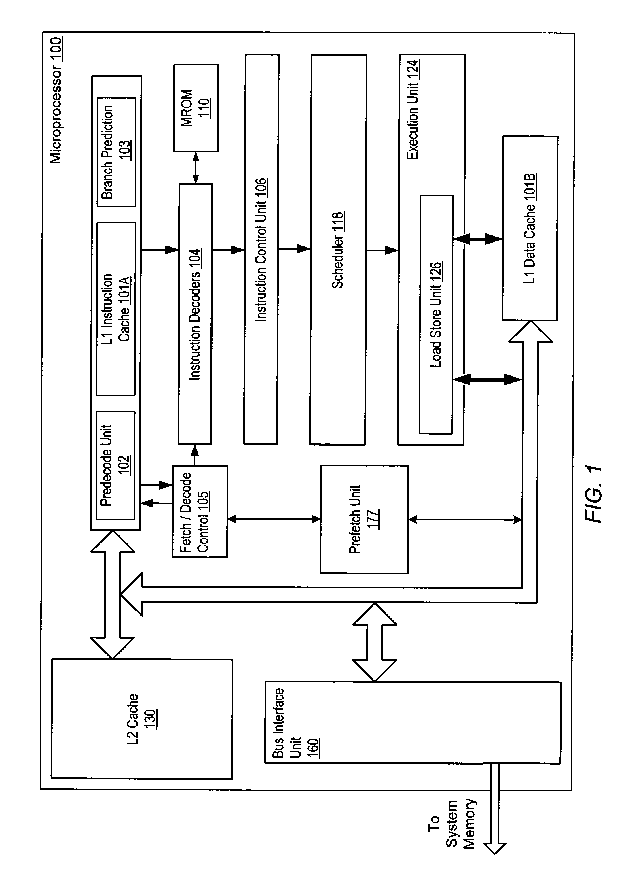
[0018]Turning now to FIG. 1, a block diagram of one embodiment of an exemplary microprocessor 100 is shown. Microprocessor 100 is configured to execute instructions stored in a system memory (not shown). Many of these instructions operate on data stored in the system memory. It is noted that the system memory may be physically distributed throughout a computer system and may be accessed by one or more microprocessors such as microprocessor 100, for example. In one embodiment, microprocessor 100 is an example of a microprocessor which implements the x86 architecture such as an Athlon™ processor, for example. However, other embodiments are contemplated which include other types of microprocessors.

[0019]In the illustrated embodiment, microprocessor 100 includes a first level one (L1) cache and a second L1 cache: an instruction cache 101A and a data cache 101B. Depending upon the implementation, the L1 cache may be a unified cache or a bifurcated cache. In either case, for simplicity, i...


PUM


Abstract

A prefetch unit for use with a cache subsystem. The prefetch unit includes a stream storage coupled to a prefetch unit. The stream storage may include a plurality of locations configured to store a plurality of entries each corresponding to a respective range of prefetch addresses. The prefetch control may be configured to prefetch an address in response to receiving a cache access request including an address that is within the respective range of prefetch addresses of any of the plurality of entries.

Description

BACKGROUND OF THE INVENTION[0001]1. Field of the Invention[0002]This invention relates to microprocessors and, more particularly, to cache prefetch mechanisms.[0003]2. Description of the Related Art[0004]Memory latency is frequently a large factor in determining the performance (e.g. instructions executed per second) of a processor in a given computer system. Over time, the operating frequencies of processors have increased dramatically, while the latency for access to dynamic random access memory (DRAM) in the typical computer system has not decreased as dramatically. Additionally, transmitting memory requests from the processor to the memory controller coupled to the memory system also requires time, which increases the memory latency. Accordingly, the number of processor clocks required to access the DRAM memory has increased, from latencies (as measured in processor clocks) of a few processor clocks, through tens of processor clocks, to over a hundred processor clocks in modern ...

Claims


Application Information

Patent Timeline
Patent Type & Authority Patents(United States)
IPC IPC(8): G06F13/28
CPCG06F12/0862G06F2212/6026
Inventor FILIPPO, MICHAEL A.PICKETT, JAMES K.ISAAC, ROGER D.
Owner ADVANCED MICRO DEVICES INC
Why Eureka
Try Eureka