Workpiece transporting apparatus and electronic component transporting apparatus

a technology of electronic components and conveying equipment, which is applied in the direction of electrical equipment, rolling carriages, basic electric elements, etc., can solve the problems of difficult to sufficiently release residual pressure and the inability of the electronic component conveying equipment to operate at high speed, so as to reduce the extra stoppage time of the conveyer table, increase the conveying efficiency of the electronic component conveying apparatus, and relieve the pressure in the exhaust hole

Active Publication Date: 2010-11-23
MURATA MFG CO LTD
View PDF11 Cites 4 Cited by
  • Summary
  • Abstract
  • Description
  • Claims
  • Application Information

AI Technical Summary

Benefits of technology

[0021]In the first embodiment, it is desirable that a width of the pressure relief groove along the conveying direction is more than or equal to 50% of the distance between one of the through-holes and the next one of the through-holes located upstream of the one of the through-hole in the conveying direction. In such a case, since the width of the pressure relief groove along the conveying direction is sufficiently large, the compressed air can be discharged for a sufficiently long period of time, and therefore, the pressure is reliably relieved.
[0031]Consequently, according to the second embodiment, undesired exhaust of an electronic component due to residual pressure can be prevented. In addition, the conveying efficiency of the electronic component conveying apparatus can be increased.

Problems solved by technology

That is, a stoppage time is needed for releasing the residual pressure and, therefore, the electronic component conveying apparatuses cannot operate at high speed.
In addition, even when the stoppage time is increased, it is still difficult to sufficiently release the residual pressure.

Method used


Image

  • Workpiece transporting apparatus and electronic component transporting apparatus
  • Workpiece transporting apparatus and electronic component transporting apparatus
  • Workpiece transporting apparatus and electronic component transporting apparatus

Examples


Embodiment Construction

Reference Numerals

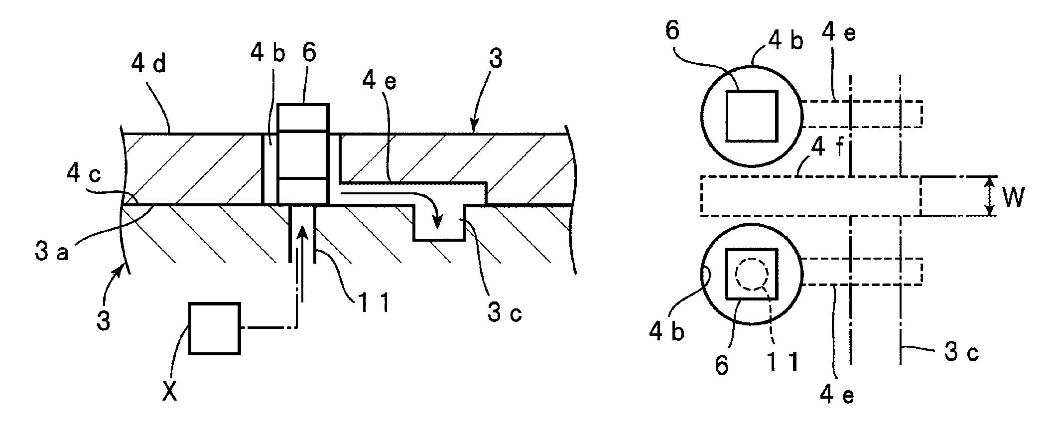
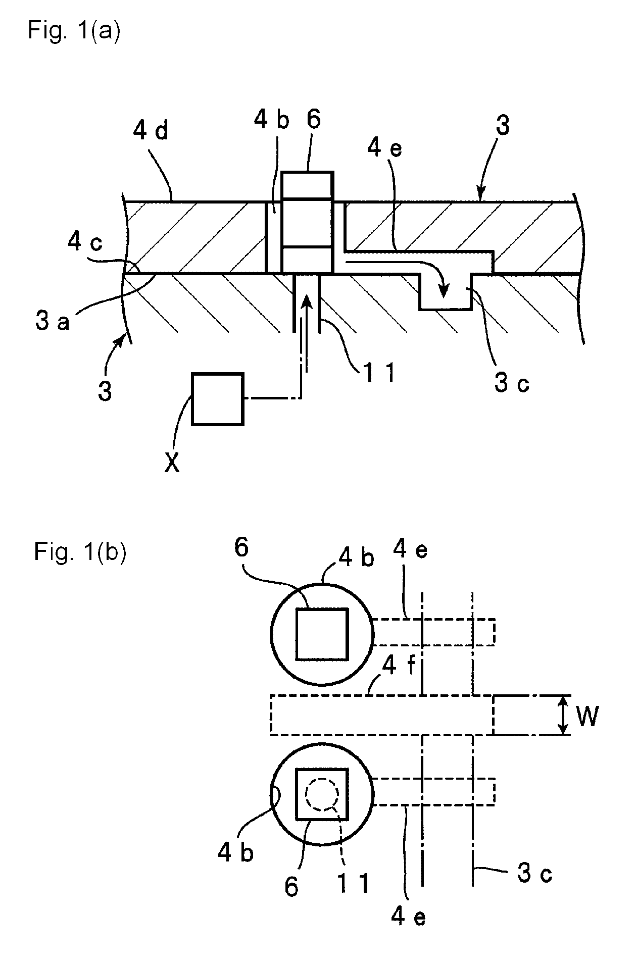
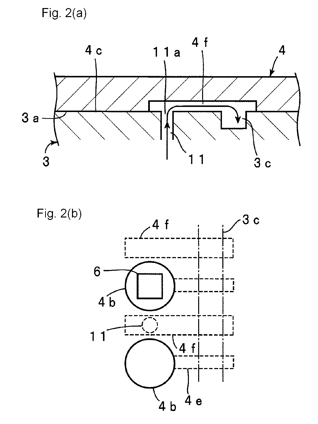
[0040]1 electronic component conveying apparatus[0041]2 base plate[0042]3 conveyer stage[0043]3a conveying surface[0044]3b, 3c, 3d suction recess portion[0045]4 conveyer table[0046]4a center shaft[0047]4b through-hole[0048]4c first surface[0049]4d second surface[0050]4e suction groove[0051]4f pressure relief groove[0052]4g pressure relief hole[0053]4h pressure relief hole[0054]5 driving unit[0055]6 electronic component[0056]7 electronic component supply unit[0057]8 characteristic measuring unit[0058]9 pickup unit[0059]10 suction source[0060]11 exhaust hole[0061]11a opening

[0062]Exemplary embodiments are described below in connection with the accompanying drawings.

[0063]FIGS. 3(a) and 3(b) are, respectively, a schematic front view of an electronic component conveying apparatus, and a schematic front view of the electronic component conveying apparatus with the conveyer table (described below) removed.

[0064]An electronic component conveying apparatus 1 includes a bas...


PUM


Abstract

An electronic component conveying apparatus is provided in which an electronic component is accommodated in a through-hole of a conveyer table and is conveyed. The electronic component can be reliably picked up from the through-hole using a compressed gas in a short time. In addition, undesired exhaust of the electronic component due to a residual compressed air can be prevented, and the conveying efficiency can be increased. In an workpiece conveying apparatus, a first surface of a conveyer table includes a pressure relief groove that extends from a location at which the pressure relief groove overlaps with an exhaust hole in a direction crossing a conveying direction and communicates with a suction recess portion when the conveyer table is rotationally driven. Alternatively, the first surface includes a pressure relief hole for relieving pressure to the atmosphere.

Description

CROSS-REFERENCE TO RELATED APPLICATIONS[0001]This is a continuation under 35 U.S.C. §111(a) of PCT / JP2007 / 059363 filed May 2, 2007, and claims priority of JP2006-154482 filed Jun. 2, 2006, both incorporated by reference.[0002]This application is related to U.S. Ser. No. 12 / 246,079, filed Oct. 6, 2008, (P / 1320-238), also incorporated by reference.BACKGROUND[0003]1. Technical Field[0004]The present disclosure relates to a workpiece conveying apparatus for conveying a plurality of electronic components, such as chip electronic components, and in particular, to a workpiece conveying apparatus and an electronic component conveying apparatus for conveying a workpiece by moving, on a conveyer stage, a conveyer table having a plurality of through-holes formed therein, each of said through-holes serving as a container portion for a workpiece.[0005]2. Background Art[0006]In general, in order to manufacture chip electronic components, after chip electronic components are produced and the chara...

Claims


Application Information

Patent Timeline
Patent Type & Authority Patents(United States)
IPC IPC(8): B65G25/00B65G29/00B65G47/22
CPCB65G47/80H01L21/67784B65G47/1485B65G47/91H05K13/02
Inventor TAKEUCHI, SATORUSASAOKA, YOSHIKAZU
Owner MURATA MFG CO LTD
Why Eureka
Try Eureka