Wear-resistant connector for a modular link conveyor belt

a technology of modular link and connector, which is applied in the field of conveyor art, can solve the problems of unfounded concerns about the cleanability of the belt, accelerate wear, and not be as strong resistance to significant shear load, and achieve the effects of enhancing wear resistance, reducing friction, and improving the cleanability of the first par

Active Publication Date: 2010-11-23
SPAN TECH
View PDF71 Cites 15 Cited by
  • Summary
  • Abstract
  • Description
  • Claims
  • Application Information

AI Technical Summary

Benefits of technology

[0009]In accordance with a first aspect of the invention, an improvement is proposed for a system in which a first part includes a surface subjected to wear as the result of sliding frictional contact with a second part. The improvement comprises a powder coating applied to the surface of the first part. The powder coating serves to reduce friction between the first and second parts, provide enhanced wear resistance to the first part, and improve cleanability of the first part.

Problems solved by technology

Despite eliminating the deleterious catenary approach prevalent in the prior art and providing the advantageous secure holding by the guide links, an aesthetic problem sometimes arises from use of the preferred stainless steel connector to connect the modular links forming the conveyor belt.
Although not a problem from a durability or reliability standpoint, the resultant appearance of the dark-colored wear particles embedded in the links can lead to unfounded concerns regarding cleanability of the belt, especially in applications where food products are being conveyed.
Particles separated from the stainless steel rod also further compound the problem by becoming embedded in the adjacent surface of the link, which then accelerate the wear.
While such polymer connectors do not create the same “black oxide” as stainless steel, they are not as able to resist significant shear loading and are also substantially more susceptible to creep.
Over time, this creep causes polymer rods to assume an irregular, or “wavy,” profile.
This profile not only compromises the appearance and operation of the belt, but also makes it more difficult to remove the rods for replacement.
Additionally, the dimensional pitch of the chain is lost, resulting in premature sprocket wear.
Besides creating an arrangement that can be impossible to clean in an easy and economical fashion, the high friction surface of the outer tube may actually cause significant wear on the links, as well as the underlying rod in the event of relative rotation.

Method used


Image

  • Wear-resistant connector for a modular link conveyor belt
  • Wear-resistant connector for a modular link conveyor belt
  • Wear-resistant connector for a modular link conveyor belt

Examples


Embodiment Construction

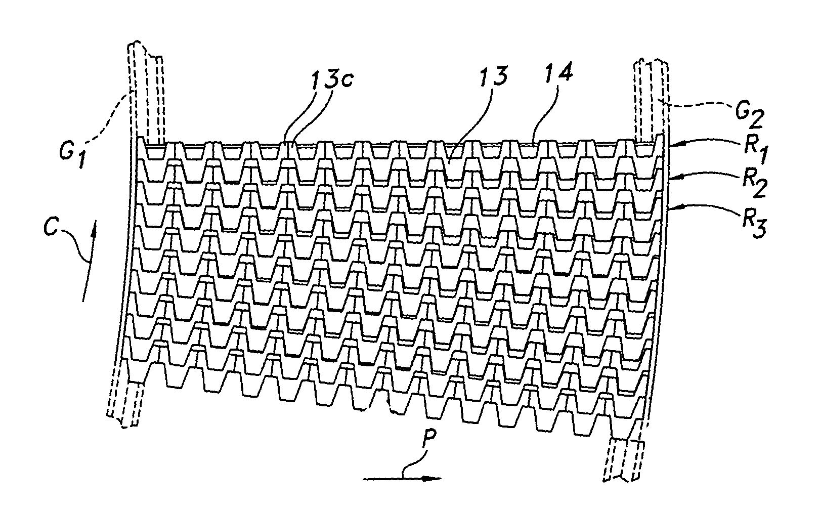
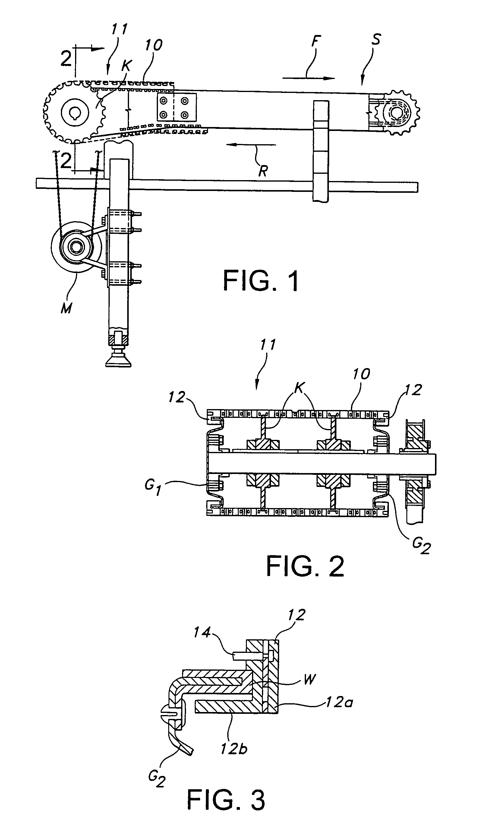
[0029]Reference is now made to FIGS. 1 and 2, which depict an overall conventional arrangement of a conveyor system S including a belt or chain 10. The chain 10 includes a conveying surface 11 for engaging and supporting articles. In this particular embodiment, the chain 10 comprises or includes modular links including side guide links 12 and intermediate links 13 arranged in spaced apart rows (see FIG. 6 and note rows R1 . . . Rn), which thus partially create the conveying surface 11. Adjacent rows R1, R2 of links are interconnected by transversely extending connectors 14, which are also referred to in the vernacular as “cross rods,”“hinge pins,” etc.

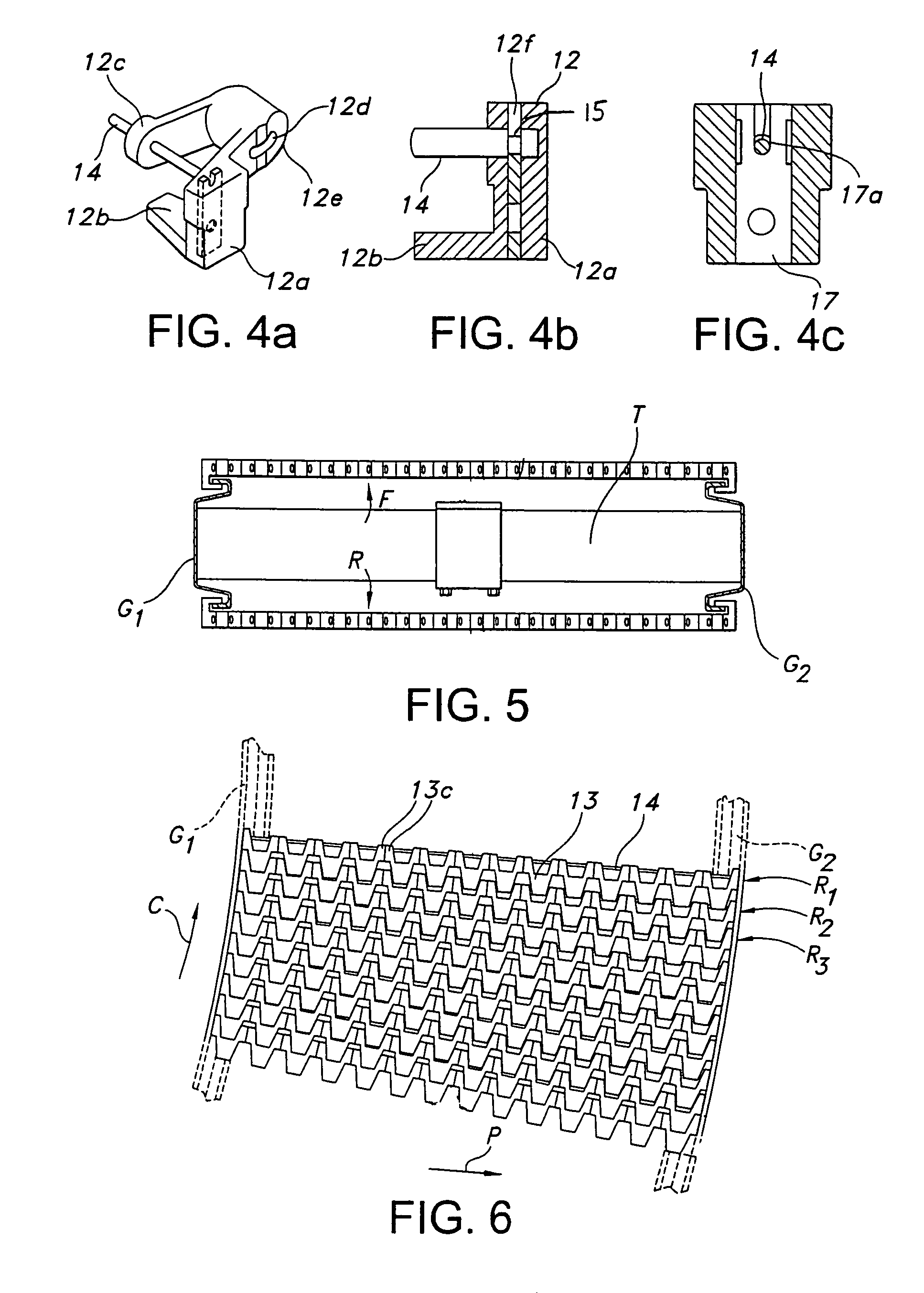
[0030]With regard to the side links 12, and as perhaps best understood by viewing FIGS. 3 and 4a-4c, each may include an outer depending arm 12a and an inwardly projecting or extending transverse tab 12b (thus creating different right handed or left handed side links, depending on the particular positioning). When present, the dependin...


PUM

PropertyMeasurementUnit
temperatureaaaaaaaaaa
diameteraaaaaaaaaa
temperatureaaaaaaaaaa

Abstract

A connector for connecting modular conveyor links to form a belt includes a rod-like core and a powder coating forming a protective shell. The core may be stainless steel and the powder coating may be nylon.

Description

[0001]This application claims the benefit of U.S. Provisional Patent Application Ser. No. 60 / 713,880, filed Sep. 2, 2005, and U.S. Provisional Patent Application Ser. No. 60 / 788,650, filed Apr. 3, 2006, the disclosures of which are incorporated herein by reference.TECHNICAL FIELD[0002]This invention relates generally to the conveyor art and, more particularly, to a wear-resistant connector for connecting modular links to form a conveyor belt.BACKGROUND OF THE INVENTION[0003]The use of modular link conveyors in industry enjoys increasing popularity. Particularly for conveying food articles or consumer products, especially in packages or in semi-packaged form, the modular link conveyor represents the overwhelming choice of those in the industry looking for a long-lasting, low cost conveying solution. In the recent past, significant advances in the development of such have been made so as to provide more efficient handling of an even larger variety of food articles, packages and contai...

Claims


Application Information

Patent Timeline
Patent Type & Authority Patents(United States)
IPC IPC(8): B65G17/06
CPCB65G17/086C09D5/03C09D5/033B65G2207/12B65G2207/26Y10T24/1628Y10T29/49826B65G2207/48
Inventor RUSSELL, MARK D.
Owner SPAN TECH
Why Eureka
Try Eureka